تم الحل ✓
categoryهندسة كهربائية
schoolبكالوريوس
event_available2026-07-14
السؤال
Transcribed Image Text:
3
Zero input response: Continuous-time system
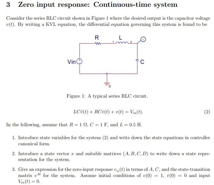
Consider the series RLC circuit shown in Figure 1 where the desired output is the capacitor voltage
v(t). By writing a KVL equation, the differential equation governing this system is found to be
Vin
R
L
w
C
Figure 1: A typical series RLC circuit.
LC (t) + RCv(t) + v(t) = Vin(t).
In the following, assume that R = 1, C = 1 F, and L = 0.5 H.
2
1. Introduce state variables for the system (2) and write down the state equations in controller
canonical form.
2. Introduce a state vector r and suitable matrices (A, B, C, D) to write down a state repre-
sentation for the system.
3. Give an expression for the zero-input response v2,(t) in terms of A, C, and the state-transition
matrix et for the system. Assume initial conditions of v(0) = 1, (0) = 0 and input
Vin(t) = 0.
check_circle الجواب — حل مفصل خطوة بخطوة
hourglass_top
🔒
الحل الكامل متاح للمشتركين
اشترك في أرشيف الأسئلة لعرض هذا الحل وآلاف الحلول المفصلة خطوة بخطوة من معلمين معتمدين.