تم الحل ✓
categoryهندسة مدنية
schoolبكالوريوس
event_available2026-07-14
السؤال
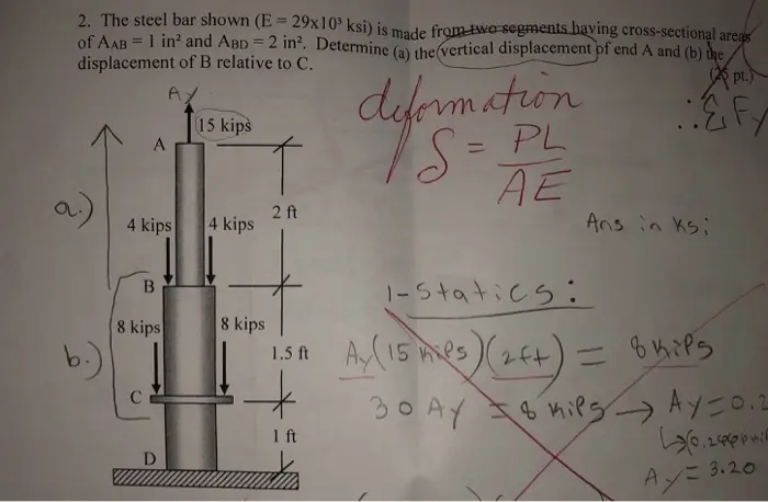
Transcribed Image Text:
2. The steel bar shown (E=29x103 ksi) is made from two segments having cross-sectional areas
of AAB = 1 in² and ABD = 2 in². Determine (a) the vertical displacement of end A and (b) the
-
displacement of B relative to C.
Ay
15 kips
A
a.)
4 kips
deformation
2 ft
S=PL
AE
4 kips
Ans in Ksi
pt.)
Fy
b.)
B
8 kips
8 kips
C
D
1.5A
+
1-Statics:
Ay (15 mies) (24+) = 8 hips
30 AY Kies Ay=0.2
1 ft
6.246
Ay=3.20
UNIAXIAL STRESS-STRAIN
Stress-Strain Curve for Mild Steel
SSSS
40.000
20.000
MECHANICS OF MATERIALS
Uniaxial Loading and Deformation
G-P/A, where
G-stress on the cross section
P-loading
cross-sectional area
YIELD STRENGTH AT 0.2
PERCENT OFFSET
A
€ = &L, where
8
-elastic longitudinal deformation
10.000
04 PERCENT
0.001 0.002 0.003 0.004
01 0.2 03
STRAIN
The slope of the linear portion of the curve equals the
modulus of elasticity.
DEFINITIONS
Engineering Strain
E-AL/L, where
€ = engineering strain (units per unit)
AL change in length (units) of member
Loriginal length (units) of member
Percent Elongation
% Elongation - (4)× 100
Percent Reduction in Area (RA)
The % reduction in area from initial area, 4, to final area,
4,, is:
%RA-(4-4)× 100
Shear Stress-Strain
Y-1/G, where
L -length of member
E=0/E=P/A
PL
True stress is load divided by actual cross-sectional area
whereas engineering stress is load divided by the initial area.
THERMAL DEFORMATIONS
8, = aL(T-T), where
8, deformation caused by a change in temperature
temperature coefficient of expansion
a
L
T
-
-length of member
final temperature
Tinitial temperature
CYLINDRICAL PRESSURE VESSEL
Cylindrical Pressure Vessel
For internal pressure only, the stresses at the inside wall are:
₁ = P
and 6,--P
For external pressure only, the stresses at the outside wall are:
and 6,--P., where
γ
shear strain
Tshear stress
o,
tangential (hoop) stress
G=shear modulus (constant in linear torsion-rotation
o,
radial stress
relationship)
P
internal pressure
G=
E
2(1+v)
where
P.
external pressure
E modulus of elasticity (Young's modulus)
■
Poisson's ratio
--(lateral strain)/(longitudinal strain)
inside radius
routside radius
For vessels with end caps, the axial stress is:
Go, and o, are principal stresses.
Flinn, Richard A. and Paul K. Troj Engineering Materials & Their Applications
4th ed., Houghton Mifflin C, B1990
76 MECHANICS OF MATERIALS
When the thickness of the cylinder wall is about one-tenth or
less of inside radius, the cylinder can be considered as thin-
walled. In which case, the internal pressure is resisted by the
hoop stress and the axial stress.
6,
Pr
and d=
where r-wall thickness and r
STRESS AND STRAIN
Principal Stresses
For the special case of a two-dimensional stress state, the
equations for principal stress reduce to
The circle drawn with the center on the normal stress
(horizontal) axis with center, C, and radius, R, where
-(༡.-॰」,
C=R=
The two nonzero principal stresses are then:
-C+R
0-C-R
Tox
+
0 0
The two nonzero values calculated from this equation are
temporarily labeled σ, and σ, and the third value σ is always
zero in this case. Depending on their values, the three roots are
then labeled according to the convention:
algebraically largest G, algebraically smallest = 0,
other G. A typical 2D stress element is shown below with
all indicated components shown in their positive sense.
(0)
The maximum inplane shear stress is t- R. However, the
maximum shear stress considering three dimensions is always
-=--
Hooke's Law
Three-dimensional case:
&- (1/E)[0,- (0,+0.)]
£,- (1/E)[0,- (0,+0,)]
-1G
Y-1G
= (1/E)[0,- 1(0,+0,)]
2-1G
Plane stress case (0,= 0):
&= (1/EX(0,-vo,)
Mohr's Circle - Stress, 2D
To construct a Mohr's circle, the following sign conventions
are used.
1. Tensile normal stress components are plotted on the
horizontal axis and are considered positive. Compressive
normal stress components are negative.
2. For constructing Mohr's circle only, shearing stresses
are plotted above the normal stress axis when the pair of
shearing stresses, acting on opposite and parallel faces of
an element, forms a clockwise couple. Shearing stresses
are plotted below the normal axis when the shear stresses
form a counterclockwise couple.
- (1/EX0,-vo)
&=-(1/EX(vo,+10)
F
1
0 0
Uniaxial case (6,-6,-0): 6,-Eɛ, or G-Eɛ, where
. . Ç - normal strain
0,0,0,- normal stress
Y Y Y shear strain
shear stress
E-modulus of elasticity
G-shear modulus
v-Poisson's ratio
Crandall, S3, and NC. Dal Action to Mechanics of Solids McGraw-Hil
New York, 1959
77 MECHANICS OF MATERIALS
TORSION
Torsion stress in circular solid or thick-walled (t>0.1r)
shafts:
The relationship between the load (w), shear (V), and moment
(M) equations are:
x)
where J-polar moment of inertia
TORSIONAL STRAIN
The limit (A/A) = r(didz)
The shear strain varies in direct proportion to the radius, from
zero strain at the center to the greatest strain at the outside of
the shaft.do/dz is the twist per unit length or the rate of twist.
G Gr(dbidz)
T = G(db) fr³d = G(d)
=d=y, where
total angle (radians) of twist
T-torque
L-length of shaft
To gives the twisting moment per radian of twist. This is
called the torsional stiffness and is often denoted by the
symbol k or c.
For Hollow, Thin-Walled Shafts
T=where
2.4
-thickness of shaft wall
=(x)
y=
--L[-w(x)]ate
M-M-(x)de
Stresses in Beams
The normal stress in a beam due to bending
0,--My-Z. where
M-the moment at the section
I - the moment of inertia of the cross section
y the distance from the neutral axis to the fiber location
above or below the neutral axis
The maximum normal stresses in a beam due to bending
0,-± Mc/1, where
e-distance from the neutral axis to the outermost fiber
of a symmetrical beam section.
0,--Mis, where
se: the elastic section modulus of the beam.
Transverse shear stress:
-Qub), where
V-shear force
Q-xy, where
-the total mean area enclosed by the shaft measured to area above the layer (or plane) upon which the
BEAMS
the midpoint of the wall.
Shearing Force and Bending Moment Sign Conventions
1. The bending moment is positive if it produces bending of
the beam concave upward (compression in top fibers and
tension in bottom fibers).
2. The shearing force is positive if the right portion of the
beam tends to shear downward with respect to the left.
desired transverse shear stress acts
-distance from neutral axis to area centroid
B-width or thickness or the cross-section
Transverse shear flow:
9-101
Tik S. ad Gleason I MacCullough Elements of Strength of Material
POSITIVE BENDING
NEGATIVE BENDING
POSITIVE HEAR
NEGATIVE SHEAR
78 MECHANICS OF MATERIALS
Deflection of Beams
Using 1/p=M/(EI).
El-M, differential equation of deflection curve
E
dd
dr
-=dM(x)/dx=V
Determine the deflection curve equation by double integration
(apply boundary conditions applicable to the deflection and or
slope).
El (dy/dx) = {M(x) dx
Ely-[M(x) dx] dx
The constants of integration can be determined from the
physical geometry of the beam.
Composite Sections
The bending stresses in a beam composed of dissimilar
materials (material I and material 2) where E,> E, are:
0,--Myl
0,--Myl, where
I, the moment of intertia of the transformed section
-the modular ratio E/E
E,-elastic modulus of material 1
E-clastic modulus of material 2
The composite section is transformed into a section composed
of a single material. The centroid and then the moment of
inertia are found on the transformed section for use in the
bending stress equations.
COLUMNS
Critical axial load for long column subject to buckling:
Euler's Formula
P-E where
(Ke)
' -unbraced column length
K-effective-length factor to account for end supports
Theoretical effective-length factors for columns include:
Pinned-pinned, K-1.0
Fixed-fixed, K=0.5
Fixed-pinned, K-0.7
Fixed-free, K=2.0
Critical buckling stress for long columns:
T
E
(KU)
where
-radius of gyration √TA
Kur effective slenderness ratio for the column
ELASTIC STRAIN ENERGY
If the strain remains within the elastic limit, the work done
during deflection (extension) of a member will be transformed
into potential energy and can be recovered.
a
If the final load is P and the corresponding elongation of
tension member is &, then the total energy U stored is equal to
the work done during loading.
U-W-P82
COMPOSITE
SECTION
MATERIAL 1
EA
MATERIAL 2
E₂ A
TRANSFORMED
SECTION
NEUTRAL
AXIS
The strain energy per unit volume is
-U/AL-6/2E
(for tension)
79 MECHANICS OF MATERIALS
check_circle الجواب — حل مفصل خطوة بخطوة
hourglass_top
🔒
الحل الكامل متاح للمشتركين
اشترك في أرشيف الأسئلة لعرض هذا الحل وآلاف الحلول المفصلة خطوة بخطوة من معلمين معتمدين.