تم الحل ✓
categoryهندسة الطيران والفضاء
schoolبكالوريوس
event_available2026-07-14
السؤال
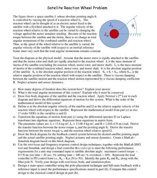
Transcribed Image Text:
Satellite Reaction Wheel Problem
The figure shows a space satellite J, whose absolute pointing angle 6.
is controlled by varying the speed of a reaction wheel J. The
reaction wheel can be thought of as an electric motor fixed to the
satellite with a flywheel attached to it. The angular velocity of the
reaction wheel relative to the satellite can be varied by changing the
voltage applied the motor armature winding. Because of the reaction
torque between the satellite and the motor, there is no change in total
angular momentum of the combined satellite and reaction wheel.
Thus, as the speed of the wheel relative to the satellite is varied, the
angular velocity of the satellite with respect to an inertial reference
frame must vary such that the total angular momentum remains constant.
Treat the diagram as the physical model. Assume that the motor stator is rigidly attached to the satellite
and that the motor rotor and shaft are rigidly attached to the reaction wheel. J, is the mass moment of
inertia of the satellite (excluding the reaction wheel, motor rotor, and motor shaft). J, is the mass moment
of inertia of the combined reaction wheel, motor rotor, and motor shaft. 8. is the absolute angular position
of the satellite. O, is the absolute angular position of the reaction wheel. 0, 0, +0s where 0s is the
relative angular position of the reaction wheel with respect to the satellite. There is viscous damping
between the satellite motion and the reaction wheel motion represented by a viscous damping coefficient
B. Neglect actuator and sensor dynamics.
a) How many degrees of freedom does this system have? Explain your answer.
b) What is the total angular momentum of this system? Explain why it must be conserved.
c) Draw free-body diagrams of the satellite and the reaction wheel. Apply Newton's 2nd Law to each
diagram and derive the differential equations of motion for this system. What is the order of the
mathematical model of this system?
d) Define co as the absolute angular velocity of the satellite and as the relative angular velocity of the
reaction wheel with respect to the satellite. Represent the mathematical model from part (c) as two
1-order ODEs in the variables co and Q.
e) Transform the equations of motion from part (c) using the differential operator D (or Laplace
transform) into algebraic equations. Represent these equations in matrix form.
f) The parameter values are: J. = 13.6 kg-m, J. = 13.6E-4 kg-m², and B = 1.01E-6 N-m-s/rad. Derive
the transfer function between the motor torque to and the pointing angle 0. Derive the transfer
function between the motor torque T and the reaction wheel relative speed .
g) Draw the block diagram for the feedback control system between the desired satellite pointing angle
and the actual satellite pointing angle. Neglect actuator and sensor dynamics. Create a MatLab /
Simulink diagram based on this block diagram.
h) Use the root-locus and frequency-response control design techniques, together with the MatLab SISO
tool and Simulink, and design a lead controller K(s+z)/(s+p) to meet the following performance
requirements for a unit step command input in satellite absolute angle: maximum control torque <
0.5 N-m; rise time < 20 sec; 1% settling time < 100 sec; % overshoot < 20%. Represent the lead
controller in PD control form i.e., Kp + Kas (N/(s+N)). Identify the gains K, and Kd, along with the
filter pole N. Verify your design with root-locus, bode, and simulation plots.
i) Design a state-space controller using the pole-placement technique and full-state feedback with a
reference input to meet the performance specifications stated in part (h). Compare this control
design to the classical control design in part (h).
check_circle الجواب — حل مفصل خطوة بخطوة
hourglass_top
🔒
الحل الكامل متاح للمشتركين
اشترك في أرشيف الأسئلة لعرض هذا الحل وآلاف الحلول المفصلة خطوة بخطوة من معلمين معتمدين.