تم الحل ✓
categoryهندسة كهربائية
schoolبكالوريوس
event_available2026-07-14
السؤال
Transcribed Image Text:
5.
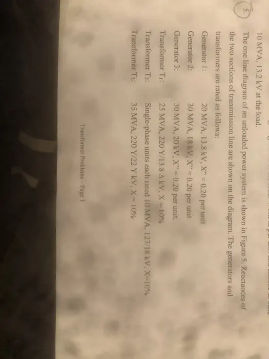
10 MVA, 13.2 kV at the load.
The one line diagram of an unloaded power system is shown in Figure 5. Reactances of
the two sections of transmission line are shown on the diagram. The generators and
transformers are rated as follows:
20 MVA, 13.8 kV, X" = 0.20 per unit
Generator 1:
Generator 2:
30 MVA, 18 kV, X"
0.20 per unit
Generator 3:
30 MVA, 20 kV, X"
0.20 per unit.
Transformer Ti:
25 MVA, 220 Y/13.8 A kV, X=10%
Transformer T2:
Single-phase units each rated 10 MVA, 127/18 kV, X=10%
Transformer T3:
35 MVA, 220 Y/22 Y kV, X = 10%
Transformer Problems - Page 1
6.
Draw the impedance diagram with all reactances marked in per unit and with letters to
indicate points corresponding to the one-line diagram.
Choose a base of 50 MVA, 13.8 kV in the circuit of generator 1.
T₁
C
B
j800
D
3
Figure 5
11000
E
Draw the impedance diagram for the power system shown in Figure 6. Mark impedances
unit Naals
check_circle الجواب — حل مفصل خطوة بخطوة
hourglass_top
🔒
الحل الكامل متاح للمشتركين
اشترك في أرشيف الأسئلة لعرض هذا الحل وآلاف الحلول المفصلة خطوة بخطوة من معلمين معتمدين.