تم الحل ✓
categoryهندسة كهربائية
schoolبكالوريوس
event_available2026-07-14
السؤال
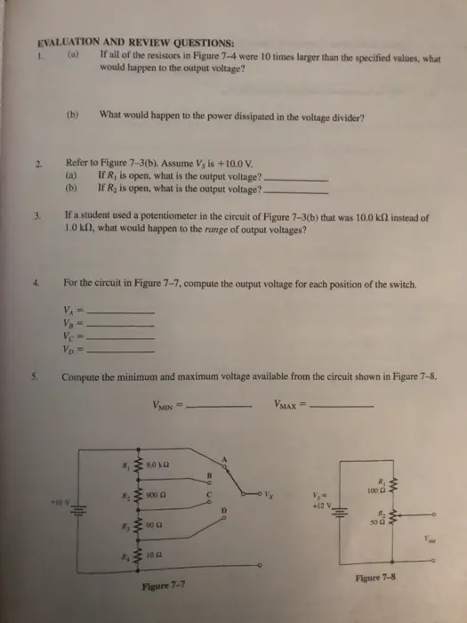
Transcribed Image Text:
EVALUATION AND REVIEW QUESTIONS:
1. (a)
If all of the resistors in Figure 7-4 were 10 times larger than the specified values, what
would happen to the output voltage?
2.
3.
(b)
What would happen to the power dissipated in the voltage divider?
Refer to Figure 7-3(b). Assume Vs is +10.0 V.
(a)
(b)
If R, is open, what is the output voltage?.
If R, is open, what is the output voltage?.
If a student used a potentiometer in the circuit of Figure 7-3(b) that was 10.0 kf instead of
1.0 kf, what would happen to the range of output voltages?
4.
For the circuit in Figure 7-7, compute the output voltage for each position of the switch.
5.
VB
Vc
Vp
Compute the minimum and maximum voltage available from the circuit shown in Figure 7-8.
VMIN=
VMAX=
R₂
+10 V
Ry
www
w
www
9.0 kQ
B
R
900 Q
100 Q
C
+12 V
D
R₂
90 Q
10 Q2
Figure 7-7
50
w
w
Figure 7-8
6. (a)
Compute the power dissipated by each resistor in Figure 7-8.
(b) Why isn't the power dissipated affected by Vour?
Figure 7-2
Voltage dividers can be made to obtain variable voltages by using a potentiometer. The full ran
of the input voltage is available at the output, as illustrated in Figure 7-3(a). If you want to limit the
of the output voltage, this can be done by using fixed resistors in series, as illustrated in Figure 7-3(b).
RI
330 N
www
ww
Vs +10 V
POT
1 ΚΩ
- Vx
+10 V
Figure 7-3
(b)
www
R2
470 2
R POTOVX
78
78
R₁
330 Q
ww
R₁₂
470 Q
R₁
680 Q
www
w
Figure 7-4
RA
1000 Q
check_circle الجواب — حل مفصل خطوة بخطوة
hourglass_top
🔒
الحل الكامل متاح للمشتركين
اشترك في أرشيف الأسئلة لعرض هذا الحل وآلاف الحلول المفصلة خطوة بخطوة من معلمين معتمدين.