تم الحل ✓
categoryهندسة كهربائية
schoolبكالوريوس
event_available2026-07-14
السؤال
Transcribed Image Text:
QUESTION 1
a. How can a silicon controlled rectifier (SCR) be turned off?
(Total 10 marks)
(1 mark)
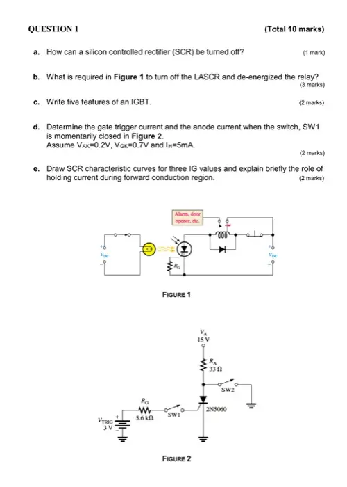
b. What is required in Figure 1 to turn off the LASCR and de-energized the relay?
(3 marks)
c. Write five features of an IGBT.
(2 marks)
d. Determine the gate trigger current and the anode current when the switch, SW1
is momentarily closed in Figure 2.
Assume VAK 0.2V, Vox=0.7V and IH-5mA.
(2 marks)
e. Draw SCR characteristic curves for three IG values and explain briefly the role of
holding current during forward conduction region.
(2 marks)
Voc
VTRIG
3V
Ra
www
5.6 k
Alarm, door
opener, etc.
FIGURE 1
330
SW2
2N5060
SWI
FIGURE 2
Voc
QUESTION 2 - (a)
The buck dc-dc converter of Figure 3 has:
60V input
0.45 duty ratio
150uF capacitor
(Total 10 marks)
530uH inductor
10kHz frequency
200 load resistance
Assuming ideal components, calculate
1.
The output voltage of the buck converter.
(2 marks)
ii.
The maximum and minimum inductor currents.
(4 marks)
iii.
The output voltage ripple.
(4 marks)
+
www
FIGURE 3
ww
QUESTION 2 - (b)
(Total 10 marks)
Design a dc-dc boost converter that will have an output of 60V from a 24V source.
Design for continuous inductor current and an output ripple voltage of less than one
percent.
The load is a resistance of 250.
Assume ideal components for this design.
You have to calculate the following:
i. Duty ratio.
ii. Minimum value of the inductor (Lmin).
iii. Inductor current (IL).
iv. Maximum and minimum currents (Imax, Imim).
(1 mark)
(2 marks)
(2 marks)
(3 marks)
V.
Output capacitor value.
(2 marks)
(Total 15 marks)
QUESTION 2 - (c)
The bridge rectifier circuit of Figure 4 has an ac source with
Vm 100 V at 60 Hz and a series RL load with R-100 and L = 10 mH.
i. Determine the average current in the load.
ii.
(2 marks)
Estimate the peak-to-peak variation in load current based on the first ac term in
the Fourier series.
(4 marks)
iii.
Determine the power absorbed by the load and the power factor of the circuit.
(3 marks)
iv. Determine the average and rms currents in the diodes.
(1 mark)
D₁₂
D₁
v,(1)-
V sin cor
D₁₂
ŹD₂
BRIDGE RECTIFIER WITH AN RL LOAD
Figure 4
QUESTION 2 -(d)
(Total 10 marks)
For the dc-ac inverter in Figure 5, Input dc voltage is 100V with 100 load.
Use inductor value of 25 mH and 50 Hz frequency.
i. Determine the amplitudes of the Fourier series terms for the square wave load
voltage.
(4 marks)
ii. The amplitudes of the Fourier series terms for the load current.
(4 marks)
iii. Power absorbed by the load.
Q1
DI
D3
Q3
Vdc
Q4
D4
D2
Q2
FULL-BRIDGE INVERTER USING IGBTS
Figure 5
(2 marks)
QUESTION 2 -(e)
i. What is a Cyclo-converter?
ii. How can the speed of an induction motor be reduced?
(Total 5 marks)
iii. The single-phase ac voltage controller of Figure 6 has a 120 Vrms, 60 Hz
source. The load resistance is 15 Q.
(1 mark)
(1 mark)
Determine the delay angle required to deliver 500 W to the load.
(3 marks)
FIGURE 6
QUESTION 3 - (a)
(Total 10 marks)
i. Silicon control rectifier (SCR) is extensively used in power control applications.
Figure 6 show how the load current through R₁ can be controlled using the
SCR gate voltage.
Draw the voltage waveform (VAK) across the SCR in Figure 6 from anode to
cathode (ground) in relation to the load current (IL) for 180°, 45° and 90°
conductions.
Assume an ideal SCR.
(7 marks)
ii. What is the voltage across the SCR if it is never triggered?
(3 marks)
R₁
R₁
10 ΚΩ
100
120 V
R₁₂
500 2
FIGURE 6
QUESTION 3 - (b)
(Total 10 marks)
i. Design a duty cycle control circuit to switch ON and OFF alternatively gates of
the IGBTs for the full-bridge dc-ac inverter.
Two resistors (R1=2.2k2, R2-4.7KQ) and a capacitor (C=0.022uF) can be used
to control the frequency as well as the duty cycle.
Calculate the frequency (fr) and duty cycle.
(5 marks)
ii. Modify your circuit such that capacitor (C-0.022uF) charges through only R1 and
discharges through R2.
(5 marks)
QUESTION 4 - (a)
(Total 10 marks)
i. Draw a block diagram of hybrid photovoltaic/wind/battery/grid system with arrows
showing the direction of energy flow.
(4 marks)
ii. Explain a method to calculate the size of a photovoltaic (PV) based energy
system for residential house with four occupants in Auckland.
(2 marks)
iii. Explain the role of a central controller for small-scale (residential) renewable
energy systems.
(2 marks)
iv. List five disadvantages of PV and wind energy generation systems.
(2 marks)
QUESTION 4 - (b)
1. Explain the following
1. Two types of solar collectors?
(Total 10 marks)
(1 mark)
ii. Types, advantages and disadvantages of energy storage systems?
iii.
Concentrated Solar Power (CSP).
(2.5 marks)
(1 mark)
(1 mark)
iv. Types of concentrated solar power.
2. Explain, how maximum power can be extracted from a Photovoltaic (PV) array
under variable solar radiation condition?
Explain with diagram.
(4.5 marks)
check_circle الجواب — حل مفصل خطوة بخطوة
hourglass_top
🔒
الحل الكامل متاح للمشتركين
اشترك في أرشيف الأسئلة لعرض هذا الحل وآلاف الحلول المفصلة خطوة بخطوة من معلمين معتمدين.