تم الحل ✓
categoryهندسة كهربائية
schoolبكالوريوس
event_available2026-07-14
السؤال
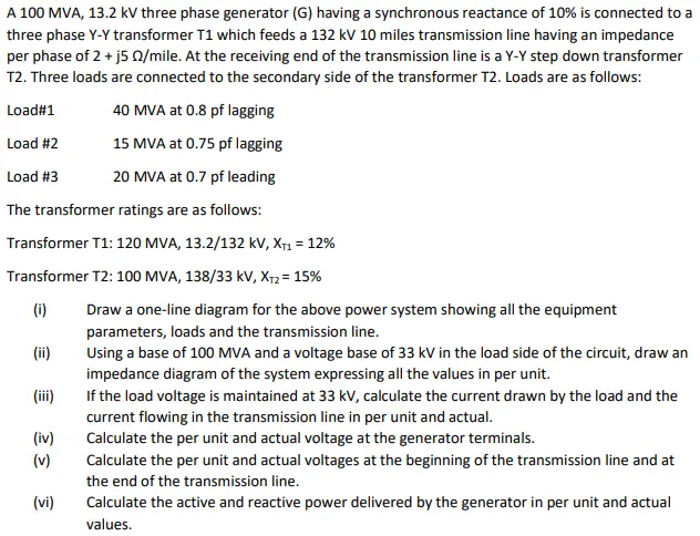
Transcribed Image Text:
A 100 MVA, 13.2 kV three phase generator (G) having a synchronous reactance of 10% is connected to a
three phase Y-Y transformer T1 which feeds a 132 kV 10 miles transmission line having an impedance
per phase of 2+ j5 /mile. At the receiving end of the transmission line is a Y-Y step down transformer
T2. Three loads are connected to the secondary side of the transformer T2. Loads are as follows:
Load#1
40 MVA at 0.8 pf lagging
Load #2
15 MVA at 0.75 pf lagging
Load #3
20 MVA at 0.7 pf leading
The transformer ratings are as follows:
Transformer T1: 120 MVA, 13.2/132 kV, XT1 = 12%
Transformer T2: 100 MVA, 138/33 kV, XT2 = 15%
Using a base of 100 MVA and a voltage base of 33 kV in the load side of the circuit, draw an
impedance diagram of the system expressing all the values in per unit.
(i)
Draw a one-line diagram for the above power system showing all the equipment
parameters, loads and the transmission line.
(ii)
(iii)
(iv)
(v)
(vi)
If the load voltage is maintained at 33 kV, calculate the current drawn by the load and the
current flowing in the transmission line in per unit and actual.
Calculate the per unit and actual voltage at the generator terminals.
Calculate the per unit and actual voltages at the beginning of the transmission line and at
the end of the transmission line.
Calculate the active and reactive power delivered by the generator in per unit and actual
values.
check_circle الجواب — حل مفصل خطوة بخطوة
hourglass_top
🔒
الحل الكامل متاح للمشتركين
اشترك في أرشيف الأسئلة لعرض هذا الحل وآلاف الحلول المفصلة خطوة بخطوة من معلمين معتمدين.