تم الحل ✓
categoryهندسة ميكانيكية
schoolبكالوريوس
event_available2026-07-13
السؤال
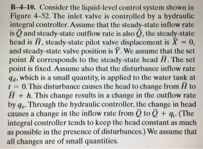
Transcribed Image Text:
B-4-10. Consider the liquid-level control system shown in
Figure 4-52. The inlet valve is controlled by a hydraulic
integral controller. Assume that the steady-state inflow rate
is and steady-state outflow rate is also Q, the steady-state
head is H, steady-state pilot valve displacement is
t =
=
0,
and steady-state valve position is Y. We assume that the set
point R corresponds to the steady-state head H. The set
point is fixed. Assume also that the disturbance inflow rate
qd, which is a small quantity, is applied to the water tank at
0. This disturbance causes the head to change from A to
H+h. This change results in a change in the outflow rate
by qo. Through the hydraulic controller, the change in head
causes a change in the inflow rate from 0 to + q. (The
integral controller tends to keep the head constant as much
as possible in the presence of disturbances.) We assume that
all changes are of small quantities.
We assume that the velocity of the power piston (valve)
is proportional to pilot-valve displacement x, or
dy
dt
=
K₁x
where K₁ is a positive constant. We also assume that the
change in the inflow rate q; is negatively proportional to the
change in the valve opening y, or
qi = -K₁y
where K,, is a positive constant.
Assuming the following numerical values for the system,
C = 2m²,
R = 0.5 sec/m²,
a = 0.25 m,
b = 0.75 m,
obtain the transfer function H(s)/Qd(s).
K₁
=
1 m²/sec
K₁ = 4 sec1
Problem 3 (20 points)
Solve problem B-4-10. Then answer the following:
1. If the head h is the input to the hydraulic controller and the output from the controller is
derive the transfer function of the controller?
2. What is the control action of this controller?
b-
Y+y
+qi
龍
9d
H+h
C (Capacitance)
Figure 4-52
Liquid-level control system.
R
(Resistance)
+40
check_circle الجواب — حل مفصل خطوة بخطوة
hourglass_top
🔒
الحل الكامل متاح للمشتركين
اشترك في أرشيف الأسئلة لعرض هذا الحل وآلاف الحلول المفصلة خطوة بخطوة من معلمين معتمدين.