تم الحل ✓
categoryهندسة حاسوب وشبكات
schoolبكالوريوس
event_available2026-07-13
السؤال
Transcribed Image Text:
3.
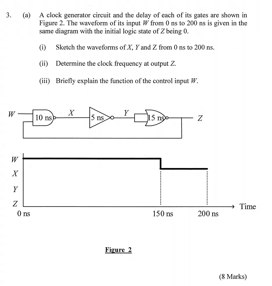
(a) A clock generator circuit and the delay of each of its gates are shown in
Figure 2. The waveform of its input W from 0 ns to 200 ns is given in the
same diagram with the initial logic state of Z being 0.
(i) Sketch the waveforms of X, Y and Z from 0 ns to 200 ns.
(ii) Determine the clock frequency at output Z.
(iii) Briefly explain the function of the control input W.
W
X
Y
10 ns)
5 ns
15 ns-
Z
W
X
> N
Y
0 ns
Figure 2
Time
150 ns
200 ns
(8 Marks)
check_circle الجواب — حل مفصل خطوة بخطوة
hourglass_top
🔒
الحل الكامل متاح للمشتركين
اشترك في أرشيف الأسئلة لعرض هذا الحل وآلاف الحلول المفصلة خطوة بخطوة من معلمين معتمدين.