تم الحل ✓
categoryهندسة حاسوب وشبكات
schoolبكالوريوس
event_available2026-07-13
السؤال
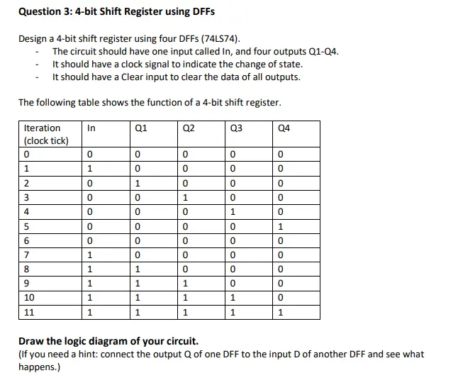
Transcribed Image Text:
Question 3: 4-bit Shift Register using DFFs
Design a 4-bit shift register using four DFFs (74LS74).
The circuit should have one input called In, and four outputs Q1-Q4.
- It should have a clock signal to indicate the change of state.
It should have a Clear input to clear the data of all outputs.
The following table shows the function of a 4-bit shift register.
Iteration
In
Q1
Q2
Q3
Q4
(clock tick)
0
0
0
0
0
0
1
1
0
0
0
0
2
0
1
0
0
0
3
0
0
1
0
0
4
0
0
0
1
0
5
0
0
0
0
1
6
0
0
0
0
0
7
1
0
0
0
0
8
1
1
0
0
0
9
1
1
1
0
0
10
1
1
1
1
0
11
1
1
1
1
1
Draw the logic diagram of your circuit.
(If you need a hint: connect the output Q of one DFF to the input D of another DFF and see what
happens.)
check_circle الجواب — حل مفصل خطوة بخطوة
hourglass_top
🔒
الحل الكامل متاح للمشتركين
اشترك في أرشيف الأسئلة لعرض هذا الحل وآلاف الحلول المفصلة خطوة بخطوة من معلمين معتمدين.