تم الحل ✓
categoryهندسة ميكانيكية
schoolبكالوريوس
event_available2026-07-13
السؤال
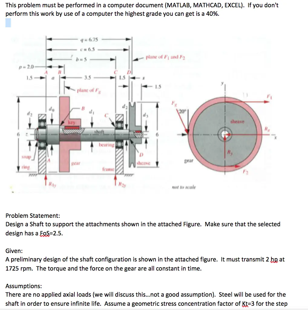
Transcribed Image Text:
This problem must be performed in a computer document (MATLAB, MATHCAD, EXCEL). If you don't
perform this work by use of a computer the highest grade you can get is a 40%.
p=2.0
1.5
snap
ring
9-6.75
c=6.5
b=5
R
C
3.5
1.5
do
key
Ray
plane of Fg
B
DI
plane of F and F
15
120°
sheave
Rx
shaft
bearing
Ry
gear
sheave
F
bear
frame
not to scale
Problem Statement:
Design a Shaft to support the attachments shown in the attached Figure. Make sure that the selected
design has a FOS=2.5.
Given:
A preliminary design of the shaft configuration is shown in the attached figure. It must transmit 2 hp at
1725 rpm. The torque and the force on the gear are all constant in time.
Assumptions:
There are no applied axial loads (we will discuss this...not a good assumption). Steel will be used for the
shaft in order to ensure infinite life. Assume a geometric stress concentration factor of Kt=3 for the step
Assumptions:
There are no applied axial loads (we will discuss this...not a good assumption). Steel will be used for the
shaft in order to ensure infinite life. Assume a geometric stress concentration factor of Kt=3 for the step
radii in bending, a geometric stress concentration factor of Kts-2 for the step radii in shear, and a
geometric stress concentration factor of Kt=4 for any keyways. It is reasonable to not know what a
key/keyway is at this point. Start by googling it. If that isn't clear, ask me and we can discuss. Note that
torsion is steady and bending stress is fully reversed. This will combine into a state of fatigue loading
that is NOT FULLY REVERSED.
Solution (start of it)
I First determine the transmitled torque from the given power and angular velocity using
equation 10.1 (p. 585).
17
2 lip 6600
P
7-
in-lb/sec
bp
2π rad/scc
= 73.1 lb in
1725 apm
60
гpm
(a)
This torque exists only over the portion of shaft between the sheave and the gear and
is uniform in magnitude over that length as shown in Figure 10-6.
2 The tangential forces on sheave and gear are found from the torque and their respec
tive raditi. A V-belt has tension on both sides, and the ratio between the force F on the
tight side and F₂ on the "slack" side is usually assumed to be about 5. The net force
associated with the driving torque is FF-F2, but the force that bends the shaft
is FF+F2. Combining these relationships gives F = 1.5F. Looking from the
shcave end:
T
73.1 lb-in
-=24.36 lb
r
3 in
F-1.5F-36.54 lb
3 The tangential force at the spur-gear tooth is
T 73.1 lb-in
Sinprehist
-
r
3 in
-24.36j lb
(b)
(c)
The spur gear has a 20° pressure angle as shown, which means that there will also be a
radial component of force at the gear tooth of
F.
= F tan (20°)=8.87 î lb
Krudial Stangen
(d)
4 We will consider the gear and sheave forces to be concentrated at their centers. Solve
for the reaction forces in the xz and yz planes using Σ Fx =0,2 My=0 and Σ Fy = 0, Σ
My=
=0 with the trial beam dimensions, a = 1.5, b=5, and c=6.5, which make p = 2
and q = 6.75.
At this point you should have enough information to make (two) FBD's. To be clear, your job is to
determine appropriate values for do, d1, d2, d3, and all radius that transition between these diameters.
check_circle الجواب — حل مفصل خطوة بخطوة
hourglass_top
🔒
الحل الكامل متاح للمشتركين
اشترك في أرشيف الأسئلة لعرض هذا الحل وآلاف الحلول المفصلة خطوة بخطوة من معلمين معتمدين.