تم الحل ✓
categoryهندسة كهربائية
schoolبكالوريوس
event_available2026-07-13
السؤال
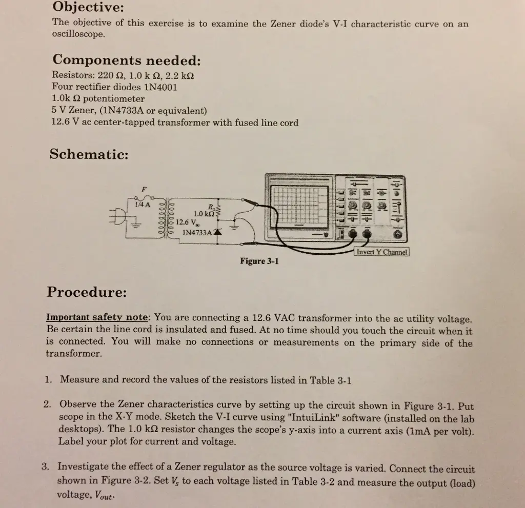
Transcribed Image Text:
Objective:
The objective of this exercise is to examine the Zener diode's V-I characteristic curve on an
oscilloscope.
Components needed:
Resistors: 220 £2, 1.0 k 2, 2.2 k
Four rectifier diodes 1N4001
1.0k 2 potentiometer
5 V Zener, (1N4733A or equivalent)
12.6 V ac center-tapped transformer with fused line cord
Schematic:
1/4 A
R.
1.0 ΚΩΣ
12.6 V
IN4733AZ
20000
44
이히 이런
Invert Y Channel
Figure 3-1
Procedure:
Important safety note: You are connecting a 12.6 VAC transformer into the ac utility voltage.
Be certain the line cord is insulated and fused. At no time should you touch the circuit when it
is connected. You will make no connections or measurements on the primary side of the
transformer.
1. Measure and record the values of the resistors listed in Table 3-1
2. Observe the Zener characteristics curve by setting up the circuit shown in Figure 3-1. Put
scope in the X-Y mode. Sketch the V-I curve using "IntuiLink" software (installed on the lab
desktops). The 1.0 k2 resistor changes the scope's y-axis into a current axis (1mA per volt).
Label your plot for current and voltage.
3. Investigate the effect of a Zener regulator as the source voltage is varied. Connect the circuit
shown in Figure 3-2. Set V, to each voltage listed in Table 3-2 and measure the output (load)
voltage, Vout
Vs
R₁
ww
220 Ω
VOUT
1/2 W
IN4733A
R₁
2.2 ΚΩ
Figure 3-2
4. From the measurements in step 3, complete Table 3-2. Apply Ohm's Law to compute the load
current, I, for each setting of the source of voltage. The voltage across R₁ (VR1) can be found
by applying Kirchhoff's Voltage Law (KVL) to the outside loop. It is the difference between
the source voltage, V, and the output voltage, Vout. Note that I, is through R₁ and can be
found using Ohm's law. Find the zener current, Iz, by applying Kirchhoff's Current law (KCL)
to the junction at the top of the zener diode.
What happens to the zener current after the breakdown voltage is reached?
5. Test the effect of a variable load resistance on a zener regulator. Construct the circuit shown
in Figure 3-3. Set the power supply to a fixed +12.0 V output and adjust the potentiometer
(R) for maximum resistance.
Vs
R₁
ww
220 Ω
1/2 W
VOUT
IN4733A
R₁₂
3 1.0 ΚΩ
Figure 3-3
6. With the potentiometer set to 1.0 k2 (maximum resistance), measure the load voltage (Vout)
and record the voltage in Table 3-3. Compute the other parameters listed on the first row as
before. (Use Ohm's law for IL, KVL for VR1, Ohm's law for Is, and KCL for Iz).
7. Set the potentiometer to each value listed in Table 3-3 and repeat step 6.
8. From the data in the Table 3-3, plot the output voltage as a function of load resistance using
"IntuiLink" software. Choose a reasonable scale factor for each axis and add labels and a title
to the plot.
Data:
Table 3-1:
Resistor
Table 3-2:
Listed value
Measured value
R₁
220 Ω
R₂
1.0 ΚΩ
220
1.00 An
RL
2.2 ΚΩ
2.00 A
Vs
Vout
IL
VR1
Is
Iz
(measured)
(computed)
(computed)
(computed)
(computed)
2.0 V
1.82V
4.0 V
3.6V
6.0 V
4.45V
8.0 V
10.0 V
5.68V
5.76V
Table 3-3:
RL
Vout
IL
(measured)
(computed)
VR1
(computed)
Is
(computed)
Iz
(computed)
1.0 ΚΩ
5.31
750 Ω
5.30
500 Ω
5.20
250 Ω
5.10
100 Ω
3.70
check_circle الجواب — حل مفصل خطوة بخطوة
hourglass_top
🔒
الحل الكامل متاح للمشتركين
اشترك في أرشيف الأسئلة لعرض هذا الحل وآلاف الحلول المفصلة خطوة بخطوة من معلمين معتمدين.