تم الحل ✓
categoryهندسة كهربائية
schoolبكالوريوس
event_available2026-07-13
السؤال
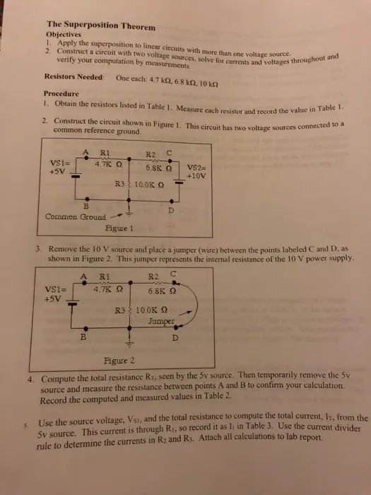
Transcribed Image Text:
The Superposition Theorem
Objectives
1. Apply the superposition to linear circuits with more than one voltage source.
2. Construct a circuit with two voltage sources, solve for currents and voltages throughout and
verify your computation by measurements.
Resistors Needed: One each: 4.7 ks2, 6.8 ks2, 10 ks
Procedure
1. Obtain the resistors listed in Table 1. Measure each resistor and record the value in Table 1.
2. Construct the circuit shown in Figure 1. This circuit has two voltage sources connected to a
common reference ground.
R1
R2 C
VS1=
+5V
4.7K Q
6.8KQ
VS2=
+10V
R3 10.0K Q
B
Common Ground
D
Figure 1
3. Remove the 10 V source and place a jumper (wire) between the points labeled C and D, as
shown in Figure 2. This jumper represents the internal resistance of the 10 V power supply.
VS1=
+5V
A R1
R2
C
w
4.7K Q
6.8K Q
R3 10.0K
Jumper
B
D
Figure 2
5.
4. Compute the total resistance RT, seen by the 5v source. Then temporarily remove the 5v
source and measure the resistance between points A and B to confirm your calculation.
Record the computed and measured values in Table 2.
Use the source voltage, Vsi, and the total resistance to compute the total current, Ir, from the
5v source. This current is through Ri, so record it as I₁ in Table 3. Use the current divider
rule to determine the currents in R2 and R3. Attach all calculations to lab report.
Record all three currents as positive values in Table 3. This will be the assigned reference for
the direction of current. Mark the magnitude and direction of the current in Figure 2.
6. Use the currents computed in step 5 and the measured resistances to calculate the expected
voltage across each resistor of Figure 2. Then connect the 5v power supply and measure the
actual voltages present in this circuit. Record the computed and measured voltages in Table 3.
Since all currents in step 5 were considered positive, all voltages in this step are also positive.
7. Remove the 5v source from the circuit and move the jumper from between points C and othe
between points A and B. Compute the total resistance between points C and D. Measure the
resistance to confirm your calculation. Record the computed and measured resistance in
Table 2.
8. Compute the current through each resistor in Figure 3. Note that this time the total current is
through R2 and divides between Ri and Rs. Mark the magnitude and direction of the current
on Figure 3. Important: Record the current as a positive current if it is in the same direction
as recorded in step 5 and as a negative current if it is in the opposite direction as in step 4.
Record the computed currents in Table 3.
R1
R2 C
w
4.7K Q
6.8K Q
VS2=
+10V
JUMPER R3 10.0K
B
D
Figure 3
9. Use the currents computed in step 8 and the measured resistances to compute the voltage
drops across each resistor. Record the computed voltage drops in Table 3. If the current
through a resistor was a positive current, record the resistor's voltage as a positive voltage. If
a current was a negative current, record the voltage as a negative voltage. Then connect the
10v source as illustrated in Figure 3, measure, and record the voltages. The measured
voltages should confirm your calculation.
10. Compute the algebraic sum of the currents and voltage listed in Table 3. Enter the computed
sums in Table 3. Then replace the jumper between A and B with the 5v source, as shown in
the original circuit in Figure 1. Measure the voltage across each resistor in this circuit. The
measured voltages should agree with the algebraic sums. Record the measured results in
Table 3.
Data
Attach work showing all calculations to lab
Table 1
Listed Measured
Value
Value
R₁
4.7 ΚΩ
R2
6.8 ΚΩ
Ra
10.0 ΚΩ
Quantity
Computed Measured
Step 4
Rr (Vsi operating alone)
Table 2 Computed and
measured resistances.
Step 7
Rr (Vs2 operating alone)
Table 3 Computed and measured current and voltage.
Computed Current
1
Computed Voltage
12
h
Step 5
V₁
V₂
V3
V₁
Measured Voltage
V₂
V3
Step 6
Step 8
Step 9
Step 10
(totals)
Conclusion
Evaluation and Review Questions
1. (a) Prove the Kirchhoff's voltage law is valid for the circuit in Figure 1. Do this by
substituting the measured algebraic sums from Table 3 into a loop equation written around
the outside loop of the circuit.
(b) Prove Kirchhoff's current law is valid for the circuit of Figure I by writing an equation
showing the currents entering a junction are equal to the currents leaving the junction.
2.
Use the signed currents computed in step 10.
If an algebraic sum in Table 3 is negative, what does this indicate?
3. What would be the effect on the final result if you had been directed to record all currents
in step 5 as negative currents instead of positive currents?
4.
In your own words, list the steps required to apply the superposition theorem.
5. Use the superposition theorem to find the current in R2 in Figure 4. Show all work.
R₁
10012
ww
VSI
20v
Vst
40v
Figure 4
R₂
2000
www
R₁
30052
check_circle الجواب — حل مفصل خطوة بخطوة
hourglass_top
🔒
الحل الكامل متاح للمشتركين
اشترك في أرشيف الأسئلة لعرض هذا الحل وآلاف الحلول المفصلة خطوة بخطوة من معلمين معتمدين.