تم الحل ✓
categoryهندسة ميكانيكية
schoolبكالوريوس
event_available2026-07-13
السؤال
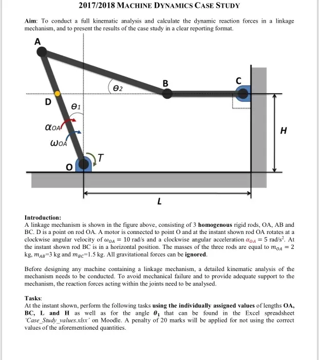
Transcribed Image Text:
2017/2018 MACHINE DYNAMICS CASE STUDY
Aim: To conduct a full kinematic analysis and calculate the dynamic reaction forces in a linkage
mechanism, and to present the results of the case study in a clear reporting format.
A
B
C
Ꮎ2
D
01
COA
WOA
T
L
H
Introduction:
A linkage mechanism is shown in the figure above, consisting of 3 homogenous rigid rods, OA, AB and
BC. D is a point on rod OA. A motor is connected to point O and at the instant shown rod OA rotates at a
clockwise angular velocity of woд 10 rad/s and a clockwise angular acceleration oд = 5 rad/s². At
the instant shown rod BC is in a horizontal position. The masses of the three rods are equal to moA = 2
kg, mAB-3 kg and mBc=1.5 kg. All gravitational forces can be ignored.
Before designing any machine containing a linkage mechanism, a detailed kinematic analysis of the
mechanism needs to be conducted. To avoid mechanical failure and to provide adequate support to the
mechanism, the reaction forces acting within the joints need to be analysed.
Tasks:
At the instant shown, perform the following tasks using the individually assigned values of lengths OA,
BC, L and H as well as for the angle ₁ that can be found in the Excel spreadsheet
"Case Study_values.xlsx' on Moodle. A penalty of 20 marks will be applied for not using the correct
values of the aforementioned quantities.
A.
Geometric Calculations:
B.
C.
D.
Determine the geometric characteristics for the mechanism geometry. All calculations should
be included in the report. Please use the notation defined in the above figure when reporting
the results to your calculations.
Calculate the followings:
(1) Distance AD.
(2) Length of rod AB.
(3) Angle 02.
Velocity Analysis:
Determine and plot:
(1) Velocity of point A.
(2) Angular velocity for rod AB.
(3) Velocity of point B.
(4) Angular velocity for rod BC.
Acceleration Analysis:
Determine and plot:
(1) Acceleration of point A.
(2) Acceleration of point B.
(3) Angular acceleration for rod AB.
(4) Angular acceleration for rod BC.
(5) Acceleration of mass centre for OA.
(6) Acceleration of mass centre for AB.
(7) Acceleration of mass centre for BC.
Dynamic Analysis:
[10]
[20]
[30]
(1) Sketch clear free-body diagrams for all the rods, taking care to show all forces (including
pin reaction forces) and accelerations for all mass centres.
(2) Using D'Alemberts Principle (or otherwise), calculate
(a) the force applied by rod AB to rod BC at point B.
(b) the torque T required by the motor to drive the mechanism at the instant shown.
[301
01= 0.3491
L= 0.348
H= 0.181
OA= 0.255
BC= 0.170
-
I
check_circle الجواب — حل مفصل خطوة بخطوة
hourglass_top
🔒
الحل الكامل متاح للمشتركين
اشترك في أرشيف الأسئلة لعرض هذا الحل وآلاف الحلول المفصلة خطوة بخطوة من معلمين معتمدين.