تم الحل ✓
categoryهندسة ميكانيكية
schoolبكالوريوس
event_available2026-07-13
السؤال
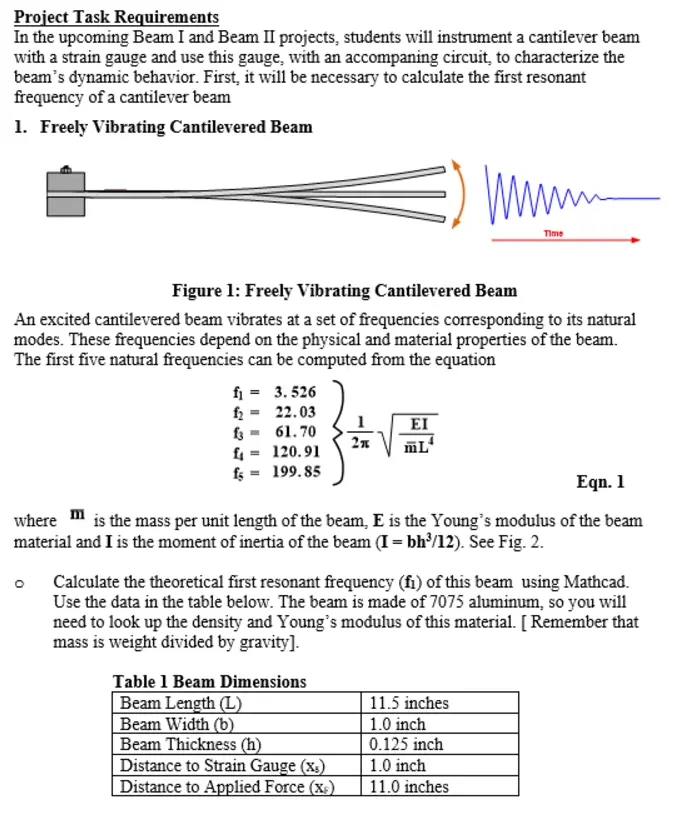
Transcribed Image Text:
Project Task Requirements
In the upcoming Beam I and Beam II projects, students will instrument a cantilever beam
with a strain gauge and use this gauge, with an accompaning circuit, to characterize the
beam's dynamic behavior. First, it will be necessary to calculate the first resonant
frequency of a cantilever beam
1. Freely Vibrating Cantilevered Beam
ww
Time
Figure 1: Freely Vibrating Cantilevered Beam
An excited cantilevered beam vibrates at a set of frequencies corresponding to its natural
modes. These frequencies depend on the physical and material properties of the beam.
The first five natural frequencies can be computed from the equation
fi = 3.526
22.03
f2
-
₤3 61.70
ΕΙ
2π
£4
ML
120.91
fs=199.85
Eqn. 1
where is the mass per unit length of the beam, E is the Young's modulus of the beam
material and I is the moment of inertia of the beam (I = bh³/12). See Fig. 2.
Calculate the theoretical first resonant frequency (fi) of this beam using Mathcad.
Use the data in the table below. The beam is made of 7075 aluminum, so you will
need to look up the density and Young's modulus of this material. [Remember that
mass is weight divided by gravity].
Table 1 Beam Dimensions
Beam Length (L)
Beam Width (b)
Distance to Strain Gauge (x)
Beam Thickness (h)
Distance to Applied Force (x)
11.5 inches
1.0 inch
0.125 inch
1.0 inch
11.0 inches.
2. Theoretical Strain Gauge Circuit Output
Assume that that simple beam bending theories are applicable. Based on these theories,
the strain, (x), of a cantilever beam subject to a point force, F, applied at the free end in
a direction perpendicular to the longitudinal axis can be calculated. Assume that there is a
strain gauge attached to the beam at point X
Xs
X
XF
F
Force applied
by a
micrometer.
L
dx
Figure 2: Cantilevered Beam
The deflection of the beam, dx, at any point, x, (0 <x<XE) is given by
Fx²
dx
6EI
(3XF-x)
Eqn. 2
where E is the Young's modulus of the beam material and I is the moment of inertia
which is given by
bh³
Eqn. 3
At the point of application of the force,
FXF³
dr
-
3EI
Eqn. 4
and at points between the force and beam end
Fx²
dx
6EI
(3L-XF)
Eqn. 5
The strain at X is given by
&
(3dph(XF-X))
2xF³
Eqn. 6
You do not know the force applied to the beam when it is depressed by the
micrometer. However, you do know that the maximum depression at the point where
the force is applied will be no more than 25 mm.Using the equations given above,
calculate the expected strain on your strain gauge for a micrometer depression values
(dr) of 0, 5, 10, 15, 20 and 25 mm. Plot the strain as a function of dr.
Then, using the gauge factor given in Appendix C, calculate the resistance change
expected in your strain gauge as a function of dr and plot.
Appendix B: Strain and the Strain Gauge
Strain is defined as the amount of deformation of a body due to an applied force. More
specifically, strain (s) is defined as the fractional change in length.
ε = SL/L
When a downward force is applied to a beam, the surface length will increase, therefore
stretching the attached strain gauge, Figure B-1.
Tension increases resistance
Insensitive to lateral force
Figure B-1: Strain Gauge
Measured
resistance
As the strain gauge is stretched, its resistance increases in proportion to the applied strain.
That is
Where:
•
·
SR/Ro GF S1/lo = GF &
SR is the strain induced change in the resistance of the strain gauge
Ro is the original resistance of the strain gauge
Sl is the strain induced change in the length of the strain gauge
•
lo is the original length of the strain gauge
•
GF is the gauge factor (sensitivity) of the strain gauge
•
Є is the actual strain induced in the strain gauge.
The strain gauge used in the Vibrating Beam I and II projects has the nominal values
Ro 120 2 and GF = 2.1.
check_circle الجواب — حل مفصل خطوة بخطوة
hourglass_top
🔒
الحل الكامل متاح للمشتركين
اشترك في أرشيف الأسئلة لعرض هذا الحل وآلاف الحلول المفصلة خطوة بخطوة من معلمين معتمدين.