تم الحل ✓
categoryالفيزياء
schoolبكالوريوس
event_available2026-07-13
السؤال
Transcribed Image Text:
Procedure:
1. Open the PHET simulation "Charges and Fields." On the upper right-hand side of the
screen, you will see several options to check off. Place a check mark in the box labeled
"Grid" and remove all other check marks.
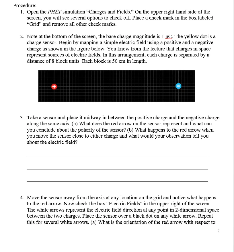
2. Note at the bottom of the screen, the base charge magnitude is 1 nC. The yellow dot is a
charge sensor. Begin by mapping a simple electric field using a positive and a negative
charge as shown in the figure below. You know from the lecture that charges in space
represent sources of electric fields. In this arrangement, each charge is separated by a
distance of 8 block units. Each block is 50 cm in length.
+
3. Take a sensor and place it midway in between the positive charge and the negative charge
along the same axis. (a) What does the red arrow on the sensor represent and what can
you conclude about the polarity of the sensor? (b) What happens to the red arrow when
you move the sensor close to either charge and what would your observation tell you
about the electric field?
4. Move the sensor away from the axis at any location on the grid and notice what happens
to the red arrow. Now check the box "Electric Fields" in the upper right of the screen.
The white arrows represent the electric field direction at any point in 2-dimensional space
between the two charges. Place the sensor over a black dot on any white arrow. Repeat
this for several white arrows. (a) What is the orientation of the red arrow with respect to
2
any of the white arrows? (b) What can you conclude about the purpose or use of the
sensor? (Hint: This can be found in the lecture and text) (c) The sensor can also generate
an electric field. Why doesn't it affect the electric field produced by the 1 nC positive and
-1 nC negative charge?
5. Describe the location where the electric field would be zero.
6. Hit the reset button on the lower right of the screen and place a check mark on the Grid
box only. Place a single positive charge on the center of the grid. On the right side, you
will find an "Equipotential" device for mapping equipotential lines. The cross-hairs are
used to locate a point on an equipotential line. The top gauge indicates voltage levels, the
two buttons below the gauge are an eraser and a pen. Using your mouse cursor, grab the
bottom of the device and position the cross-hairs 50 cm to the right of the positive charge.
Draw an equipotential line at that point by clicking on the pen button. Note: For this
exercise the potentials do not need to be precise; the patterns will still be evident if you
are within +/- 0.5 V. (a) What is the voltage measure at that point? Now move the cross-
hairs of the device along the path (in green). (b) What do you notice about the voltage
readings along the path?
7. Repeat the process of drawing the equipotential lines for two additional paths at 100 cm
and 150 cm. (a) What are the voltage measurements for 100 cm and 150 cm? (b) What
is the trend of voltage measurements as you move from 50 cm to 100cm to 150 cm
(c) Now click on the Electric Field box on the upper right. In terms of an angle, what is
the orientation of the electric field lines with respect to the equipotential lines?
Part II: Electric Potential
1. Reset the simulation. Add a positive and negative charge 300 cm apart as shown in the
diagram below. Plot equipotential lines starting at 0 (midway between the two charges),
+5V, +10V, +20V, +30V. Then at -5V, -10V, -20V, -30V. Again for this exercise, the
potentials do not need to be precise; the patterns will still be evident if you are within +/-
0.5 V.
(a) Are the equipotential lines evenly spaced (this would suggest a linear relationship) or
exponential?
(b) Use the snipping tool to copy and paste a snapshot of your result here.
2. Create a simulation of two parallel charged plates, similar to the one shown below. The
separation is 400 cm. Each is equally charged (+ and -)
a) Click on the "Electric Field" box. What do you notice about the field lines in the central
region between the plates?
b) Draw equipotential lines at 50 cm (1 block) intervals from one plate to the other. What do
you notice about the equipotential lines compared to the electric field lines? Give a brief
description. Use the Snipping Tool to cut and page the image of your parallel plates here.
c) Suppose you place a positively charged particle a distance 50 cm from the positive plate and
half-way down the plate. Describe the motion (path and acceleration) of the charge.
d) In the space below, calculate the final velocity VA of the particle just before it reaches the
negative plate, assuming it starts from rest. Refer to chapter 17 sections 2 to 4. You will
need to measure the potential at the 50 cm mark from the positive plate (the charge's initial
position) and at the point where the charge would make contact with the negative plate. Use
the following given information:
m₁ = 5.0 × 10⁻³⁰
9₁ = 1.6 × 10⁻¹⁹ c
check_circle الجواب — حل مفصل خطوة بخطوة
hourglass_top
🔒
الحل الكامل متاح للمشتركين
اشترك في أرشيف الأسئلة لعرض هذا الحل وآلاف الحلول المفصلة خطوة بخطوة من معلمين معتمدين.