تم الحل ✓
categoryهندسة حاسوب وشبكات
schoolبكالوريوس
event_available2026-07-13
السؤال
Transcribed Image Text:
Add
RegDst
Branch
MemRead
Instruction [31-26]
MemtoReg
Control
ALUOP
MemWrite
ALUSrc
Shift
left 2
ALU
Addresult
RegWrite
Instruction [25-21]
Read
PC
Read
address
register 1 Read
Instruction [20-16]
Read
data 1
Instruction
[31-0]
Instruction
register 2
M
Write
Read
Instruction [15-11] x
register data 2
Zero
ALU ALU
Read
Address
result
data
memory
Write
3x
data Registers
Write
data memory
Data
Instruction [15-0]
16
Sign- 32
extend
ALU
control
Instruction [5-0]
(MO)
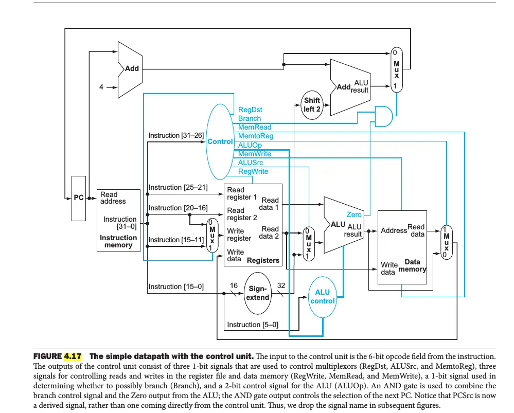
FIGURE 4.17 The simple datapath with the control unit. The input to the control unit is the 6-bit opcode field from the instruction.
The outputs of the control unit consist of three 1-bit signals that are used to control multiplexors (RegDst, ALUSrc, and MemtoReg), three
signals for controlling reads and writes in the register file and data memory (RegWrite, MemRead, and MemWrite), a 1-bit signal used in
determining whether to possibly branch (Branch), and a 2-bit control signal for the ALU (ALUOP). An AND gate is used to combine the
branch control signal and the Zero output from the ALU; the AND gate output controls the selection of the next PC. Notice that PCSrc is now
a derived signal, rather than one coming directly from the control unit. Thus, we drop the signal name in subsequent figures.
check_circle الجواب — حل مفصل خطوة بخطوة
hourglass_top
🔒
الحل الكامل متاح للمشتركين
اشترك في أرشيف الأسئلة لعرض هذا الحل وآلاف الحلول المفصلة خطوة بخطوة من معلمين معتمدين.