تم الحل ✓
categoryهندسة حاسوب وشبكات
schoolبكالوريوس
event_available2026-07-13
السؤال
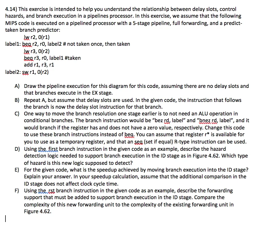
Transcribed Image Text:
4.14) This exercise is intended to help you understand the relationship between delay slots, control
hazards, and branch execution in a pipelines processor. In this exercise, we assume that the following
MIPS code is executed on a pipelined processor with a 5-stage pipeline, full forwarding, and a predict-
taken branch predictor:
Iw r2, 0(r1)
label1: beg r2, r0, label2 # not taken once, then taken
lw r3, 0(r2)
beg r3, r0, label1 #taken
add r1, r3, r1
label2: sw r1, 0(r2)
A) Draw the pipeline execution for this diagram for this code, assuming there are no delay slots and
that branches execute in the EX stage.
B) Repeat A, but assume that delay slots are used. In the given code, the instruction that follows
the branch is now the delay slot instruction for that branch.
C) One way to move the branch resolution one stage earlier is to not need an ALU operation in
conditional branches. The branch instruction would be "bez rd, label" and "bnez rd, label", and it
would branch if the register has and does not have a zero value, respectively. Change this code
to use these branch instructions instead of beg. You can assume that register r* is available for
you to use as a temporary register, and that an sea (set if equal) R-type instruction can be used.
D) Using the first branch instruction in the given code as an example, describe the hazard
detection logic needed to support branch execution in the ID stage as in Figure 4.62. Which type
of hazard is this new logic supposed to detect?
E) For the given code, what is the speedup achieved by moving branch execution into the ID stage?
Explain your answer. In your speedup calculation, assume that the additional comparison in the
ID stage does not affect clock cycle time.
F) Using the rst branch instruction in the given code as an example, describe the forwarding
support that must be added to support branch execution in the ID stage. Compare the
complexity of this new forwarding unit to the complexity of the existing forwarding unit in
Figure 4.62.
IF.Flush
and $12, $2, $5
beq $1, $3,7
sub $10, $4, $8
before<1>
before<2>
PC
Instruction
44 memory
Clock 3
IFAD
44
Control
Hazard
detection
unit
72
$1
sign
atand
Registers
IDEX
WB
EX/MEM
M
EX
MEM/WB
WB
ALU
M
$3
$8
Data
memory
10
Forwarding
unit
Iw $4, 50($7)
Bubble (nop)
beq $1, $3,7
sub $10,...
before<1>
IF.Flush
Clock 4
Instruction
memory
IF ID
72
Control
Hazard
detection
unit
Chr
(part 2)
and
ID/EX
WB
EX/MEM
M
WB
MEM/WB
0->
WB
EX
Registers
$3
ALU
Forwarding
unit
10
Data
memory
FIGURE 4.62 The ID stage of clock cycle 3 determines that a branch must be taken, so it selects 72 as the next PC
address and zeros the Instruction fetched for the next clock cycle. Clock cycle 4 shows the instruction at location 72 being
fetched and the single bubble or nop instruction in the pipeline as a result of the taken branch. (Since the nop is really sll $0, $0, 0, it's
arguable whether or not the ID stage in clock 4 should be highlighted.)
check_circle الجواب — حل مفصل خطوة بخطوة
hourglass_top
🔒
الحل الكامل متاح للمشتركين
اشترك في أرشيف الأسئلة لعرض هذا الحل وآلاف الحلول المفصلة خطوة بخطوة من معلمين معتمدين.