تم الحل ✓
categoryهندسة كهربائية
schoolبكالوريوس
event_available2026-07-13
السؤال
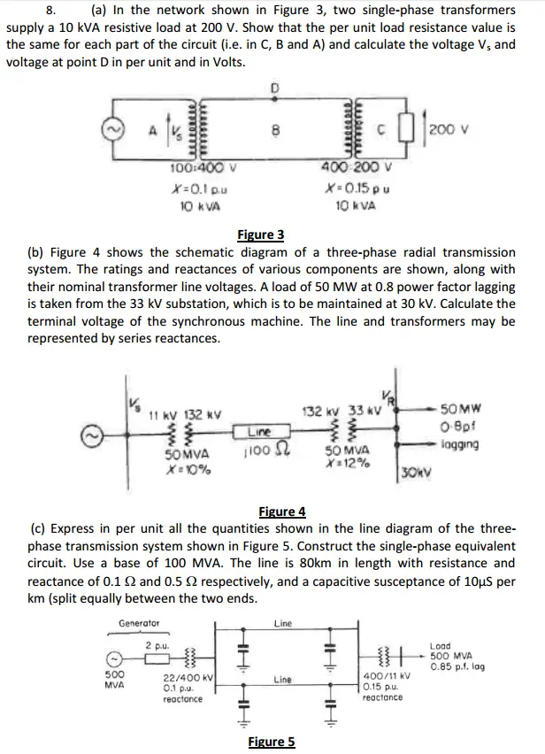
Transcribed Image Text:
8.
(a) In the network shown in Figure 3, two single-phase transformers
supply a 10 kVA resistive load at 200 V. Show that the per unit load resistance value is
the same for each part of the circuit (i.e. in C, B and A) and calculate the voltage V, and
voltage at point D in per unit and in Volts.
100:400 V
X=0.1 p.u
10 kVA
B
Figure 3
200 v
400-200 V
X=0.15 pu
10 kVA
(b) Figure 4 shows the schematic diagram of a three-phase radial transmission
system. The ratings and reactances of various components are shown, along with
their nominal transformer line voltages. A load of 50 MW at 0.8 power factor lagging
is taken from the 33 kV substation, which is to be maintained at 30 kV. Calculate the
terminal voltage of the synchronous machine. The line and transformers may be
represented by series reactances.
11 kV 132 kV
132 kV 33 kV
50MW
Line
O-8pf
50MVA
1100 Ω
X=10%
३.
50 MVA
X=12%
logging
30KV
Figure 4
(c) Express in per unit all the quantities shown in the line diagram of the three-
phase transmission system shown in Figure 5. Construct the single-phase equivalent
circuit. Use a base of 100 MVA. The line is 80km in length with resistance and
reactance of 0.12 and 0.5 2 respectively, and a capacitive susceptance of 10μS per
km (split equally between the two ends.
500
MVA
Generator
2 p.u.
22/400 kV
0.1 p.u
reactance
HHHH
Line
Line
HHHH.
Load
500 MVA
0.85 p.f. lag
400/11 kV
0.15 p.u
reactance
Figure 5
check_circle الجواب — حل مفصل خطوة بخطوة
hourglass_top
🔒
الحل الكامل متاح للمشتركين
اشترك في أرشيف الأسئلة لعرض هذا الحل وآلاف الحلول المفصلة خطوة بخطوة من معلمين معتمدين.