تم الحل ✓
categoryهندسة الطيران والفضاء
schoolبكالوريوس
event_available2026-07-15
السؤال
Transcribed Image Text:
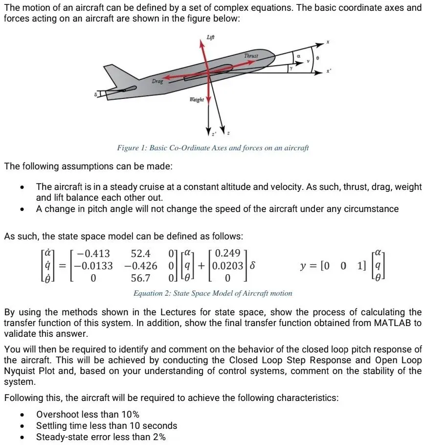
The motion of an aircraft can be defined by a set of complex equations. The basic coordinate axes and
forces acting on an aircraft are shown in the figure below:
Lift
Drag
Weight
Thrust
a
e
Figure 1: Basic Co-Ordinate Axes and forces on an aircraft
The following assumptions can be made:
The aircraft is in a steady cruise at a constant altitude and velocity. As such, thrust, drag, weight
and lift balance each other out.
A change in pitch angle will not change the speed of the aircraft under any circumstance
As such, the state space model can be defined as follows:
Lė
1-1-0.03
-0.413
q=-0.0133
52.4 01
-0.426 0
56.7 0]
0.249
+0.0203 8
0
y=[001] q
Equation 2: State Space Model of Aircraft motion
By using the methods shown in the Lectures for state space, show the process of calculating the
transfer function of this system. In addition, show the final transfer function obtained from MATLAB to
validate this answer.
You will then be required to identify and comment on the behavior of the closed loop pitch response of
the aircraft. This will be achieved by conducting the Closed Loop Step Response and Open Loop
Nyquist Plot and, based on your understanding of control systems, comment on the stability of the
system.
Following this, the aircraft will be required to achieve the following characteristics:
• Overshoot less than 10%
Settling time less than 10 seconds
Steady-state error less than 2%
Implement either a P, PI or PID controller to the pitch response in order to achieve the above
characteristic requirements, displaying the Closed Loop step response in your report and critically
analysing the suitability of the chosen controller.
Finally, with the chosen controller implemented, produce a Nyquist Plot and, based on your
understanding of control systems, comment on the stability of the system.
Submission Requirements:
A 4 page report giving an executive summary of the following:
•
•
•
•
The transfer function calculated by hand for the system from the State Space Model,
showing the steps for achieving this as well as the commands required to obtain the
same transfer function in MATLAB for validation
The identified Overshoot, 95% Settling Time and Steady State Error of the aircraft before
the implementation of a suitable controller.
The Nyquist Plot of the original system, commenting on the stability of the system given
the Gain and Phase margin produced.
The implementation of a P, PI and PID Controller, critically analysing the suitability of
each controller and whether they would be suitable.
• The identified Overshoot, Settling Time and Steady State Error of the aircraft after the
implementation of a suitable controller.
•
The Nyquist Plot of the controller-based system, commenting on the stability of the
system given the Gain and Phase margin produced.
check_circle الجواب — حل مفصل خطوة بخطوة
hourglass_top
🔒
الحل الكامل متاح للمشتركين
اشترك في أرشيف الأسئلة لعرض هذا الحل وآلاف الحلول المفصلة خطوة بخطوة من معلمين معتمدين.