تم الحل ✓
categoryالهندسة الكهربائية
schoolبكالوريوس
event_available2026-07-15
السؤال
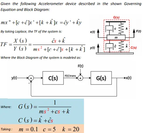
Transcribed Image Text:
Given the following Accelerometer device described in the shown Governing
Equation and Block Diagram:
mx +[c+]x +[k+k]x =cy*+ky
By taking Laplace, the TF of the system is:
G(s)
C
x(t)
F(t)
X (s)
TF
Y (s)
ĉs + k
ms² +[c+]s +[k+k] y(t)
Where the Block Diagram of the system is modeled as:
F(t)
Ft) trans,
y(t)-
C(s)
G(s)
→x(t)
1
Where:
G(s)=
ms²+cs + k
Taking:
C (s) = k +cs
m=0.1 c 5 k = 20
C(s)
Q1: For the following case of the above system. Write a MATLAB Code performing
the below requirements:
F(t)
G(s)
Filtrans
y(t)-
C(s)
G(s)
→x(t)
C
x(t)
F(t)
Where:
F(t)=0
c=0
y(t)
C(s)
C(s)=k
1. Find the open loop step response for "G(s) given above" for the time range [0:0.01:6].
2. Sketch the Root Locus Diagram for G(s) assuming (k-1) and evaluate the following:
• By dragging the "Data Cursor" over the root locus diagram, find the value of
gain "K" that guarantees a Damping-Ratio near (0.82) and Overshoot near
(1.0 %).
• What are the closed loop poles of this value of "k". (The Data Cursor should
show the info)
Show the closed loop step response at this value of "k" for time = [0,6].
[Note the fast response but also, note the Steady-state error]
3. Plot the closed loop step response for a value of "k"=200.
4. Sketch the Bode Plot for the closed loop system at "k" = 200.
check_circle الجواب — حل مفصل خطوة بخطوة
hourglass_top
🔒
الحل الكامل متاح للمشتركين
اشترك في أرشيف الأسئلة لعرض هذا الحل وآلاف الحلول المفصلة خطوة بخطوة من معلمين معتمدين.