تم الحل ✓
categoryهندسة الحاسبات
schoolبكالوريوس
event_available2026-07-15
السؤال
Transcribed Image Text:
4.1 OBJECTIVE
SR LATCH & D LATCH
In this experiment we will construct a few simple latch circuits, and realize the truth tables.
4.2 EQUIPMENT LIST
.
Digital Training set Y-0039,
Logic Gates: 7404 Inverter, 7400 NAND gate, 7402 NOR gate, 7408 AND gate
4.3 PRELIMINARY WORK
1. What is D Latch? Explain.
4.4 PROCEDURE
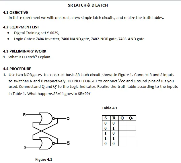
1. Use two NOR gates to construct basic SR latch circuit shown in Figure 1. Connect R and S inputs
to switches A and B respectively. DO NOT FORGET to connect Vcc and Ground pins of ICs you
used. Connect and Q and Q' to the Logic Indicator. Realize the truth table according to the inputs
in Table 1. What happens SR-11 goes to SR=00?
Figure 4.1
Table 4.1
SRQQ
00
0
1
1
0
1
1
ā
0
0
2. Use two AND gates, two NOR gates and one INVERTER to construct the D latch circuit shown in
Figure 2. Connect D and E (enable) to switches A and B respectively. DO NOT FORGET to connect Vcc
and Ground pins of ICs you used. Connect Q and Q' to the Logic Indicator. Realize the truth
table according to the inputs in Table 2.
E
Figure 4.2 D Latch
Altınbaş University
Departmant of Electrical and Electronics Engineering
Q
1
Table 4.2
ED
0 X
10
1
1
Q
QComment
EE242 Digital Systems Laboratory
4.5 QUESTIONS
1. What is level sensitive SR latch?
2. Draw D latch and give the outputs of the gates (every gate) for some inputs.
3. What is the problem when SR-11 then SR=00 in a basic SR latch? How can you solve this
problem?
4. Give some information about D latch.
check_circle الجواب — حل مفصل خطوة بخطوة
hourglass_top
🔒
الحل الكامل متاح للمشتركين
اشترك في أرشيف الأسئلة لعرض هذا الحل وآلاف الحلول المفصلة خطوة بخطوة من معلمين معتمدين.