تم الحل ✓
categoryالهندسة الكهربائية
schoolبكالوريوس
event_available2026-07-15
السؤال
Transcribed Image Text:
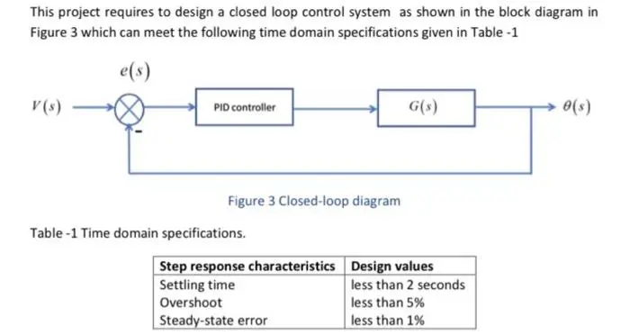
This project requires to design a closed loop control system as shown in the block diagram in
Figure 3 which can meet the following time domain specifications given in Table -1
e(s)
V(s)
PID controller
G(s)
Figure 3 Closed-loop diagram
Table -1 Time domain specifications.
Step response characteristics
Settling time
Overshoot
Steady-state error
Design values
less than 2 seconds
less than 5%
less than 1%
0(s)
Closed Loop System
With reference to Figure 3.
Q8. Derive the transfer function of the system closed loop system.
Q9. Obtain the step response of the system with time domain parameters overshoot, settling
time, peak time, and the steady-state error shown Figure 3 for the following scenarios
I.
P-controller Proportional constant (Kp) = 50
II. P-controller Proportional constant (Kp) = 100,
III.
IV.
V.
VI.
P-controller Proportional constant (Kp) = 150
Pl controller Kp = 75 and Ki = 1
Pl controller Kp = 75 and Ki = 100
Discuss your results
Q10. By incorporating a derivative constant in the PID controller with following cases
I.
Kp = 75, K = 200, K = 1
II.
Kp = 75, K = 200, Ka = 5
Kp = 75, Ki = 200, Ka = 10
III.
Calculate the overshoot, settling time, and steady-state error in this case. Are the results
acceptable? If not, explain which specification needs to be improved.
Simulink Model
Q11. Develop a Simulink model outlining all the elements of the block diagram in Figure (2) for
the unstable second order control system). Use the Simulink block PID from Matlab/Simulink
library as a controller. Obtain the time reponse of the system with time domain specifciations
in the Table -1
General
Q12. Discuss the effect of each of the PID parameters on the dynamics of a closed-loop
system and demonstrate how to use a PID controller to improve a system's performance
check_circle الجواب — حل مفصل خطوة بخطوة
hourglass_top
🔒
الحل الكامل متاح للمشتركين
اشترك في أرشيف الأسئلة لعرض هذا الحل وآلاف الحلول المفصلة خطوة بخطوة من معلمين معتمدين.