تم الحل ✓
categoryهندسة ميكانيكية
schoolبكالوريوس
event_available2026-07-15
السؤال
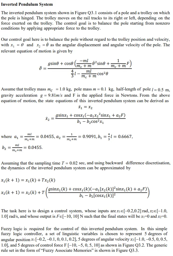
Transcribed Image Text:
Inverted Pendulum System
The inverted pendulum system shown in Figure Q3.1 consists of a pole and a trolley on which
the pole is hinged. The trolley moves on the rail tracks to its right or left, depending on the
force exerted on the trolley. The control goal is to balance the pole starting from nonzero
conditions by applying appropriate force to the trolley.
Our control goal here is to balance the pole without regard to the trolley position and velocity,
with x₁ = 0 and x2 = as the angular displacement and angular velocity of the pole. The
relevant equation of motion is given by
gsino + cose
-ml
mc+m
1
ė²sino +
9 =
mc + m
ml
-
cos20
mc + m
Assume that trolley mass mc = 1.0 kg, pole mass m = 0.1 kg, half-length of pole / = 0.5 m,
gravity acceleration g = 9.81m/s and F is the applied force in Newtons. From the above
equation of motion, the state equations of this inverted pendulum system can be derived as
x₁ = X2
x₂ =
gsinx₁+cosx₁(-a₁x2² sinx₁ + a₂F)
b₁ - b₂cos²x1
where a₁ =
ml
mc+m
= 0.0455, a₂
mc+m
; = 0.9091, b₁ = 1 = 0.6667,
ml
b₂
=
= 0.0455.
mc+m
Assuming that the sampling time T = 0.02 sec, and using backward difference discretisation,
the dynamics of the inverted pendulum system can be approximated by
x₁(k + 1) = x₁(k) + Tx₂(k)
(gsinx₁
x2(k+1)=x2(k) +T
(k)+cosx₁(k)(-a₁[x₂(k)]²sinx₁(k) + α₂F)`
b₁-b₂ [cosx1(k)]²
The task here is to design a control system, whose inputs are xie[-0.2,0.2] rad, x2 = [-1.0,
1.0] rad/s, and whose output is Fe[-10, 10] N such that the final states will be x1=0 and x2=0.
Fuzzy logic is required for the control of this inverted pendulum system. In this simple
fuzzy logic controller, a set of linguistic variables is chosen to represent 5 degrees of
angular position xi [-0.2,-0.1, 0, 0.1, 0.2], 5 degrees of angular velocity x2 [-1.0, -0.5, 0, 0.5,
1.0], and 5 degrees of control force F [-10, -5, 0, 5, 10] as shown in Figure Q3.2. The generic
rule set in the form of "Fuzzy Associate Memories" is shown in Figure Q3.3.
The initial states of this inverted pendulum system are given to
xi(1)
0.15 rad and x2(1) = -0.4 rad/s.
3.1 If the Centre of Area (COA) defuzzification strategy is used with the fire strength ai
of the i-th rule calculated from
min(ux₁(x1), Hx(x2))
determine the defuzzified control force F(1) and the next state vector [x1(2), x2(2)].
[20 marks]
3.2 If Mean of Maximum (MOM) defuzzification strategy is used with the fire strength ai
of the i-th rule calculated from
determine the defuzzified control force F(1) and the next state vector [x1(2), x2(2)]
Figure Q3.1 An inverted pendulum system
[20 marks]
Control Force (F)
Displacement (x1)
Velocity (x2)
NM
NS
ZE
PS
PM
-0.2
-0.15
-0.1
-0.05
°
0.05
0.1
0.15
0.2
NM
NS
ZE
PS
PM
1
0.5
OT
....
-0.8 -0.6
-0.4
-0.2
10
0.2
0.4
0.6
0.8
1
NM
NS
ZE
PS
PM
1
0.5
-10
-8
-6
-2
6
8
10
Figure Q3.2 Membership functions of an inverted pendulum system
Angular Velocity (✗2)
Displacement (X1)
NM NS ZE PS
PM
NM
PM PM
PM
PS
ZE
NS
PM
PM
PS
ZE
NS
ZE
PM
PS
ZE
NS
NM
PS
PS ZE NS NM
NM
PM
ZE NS NM NM NM
Figure Q3.3 Generic Fuzzy Associative Memories
10
check_circle الجواب — حل مفصل خطوة بخطوة
hourglass_top
🔒
الحل الكامل متاح للمشتركين
اشترك في أرشيف الأسئلة لعرض هذا الحل وآلاف الحلول المفصلة خطوة بخطوة من معلمين معتمدين.