تم الحل ✓
categoryالهندسة الكهربائية
schoolبكالوريوس
event_available2026-07-15
السؤال
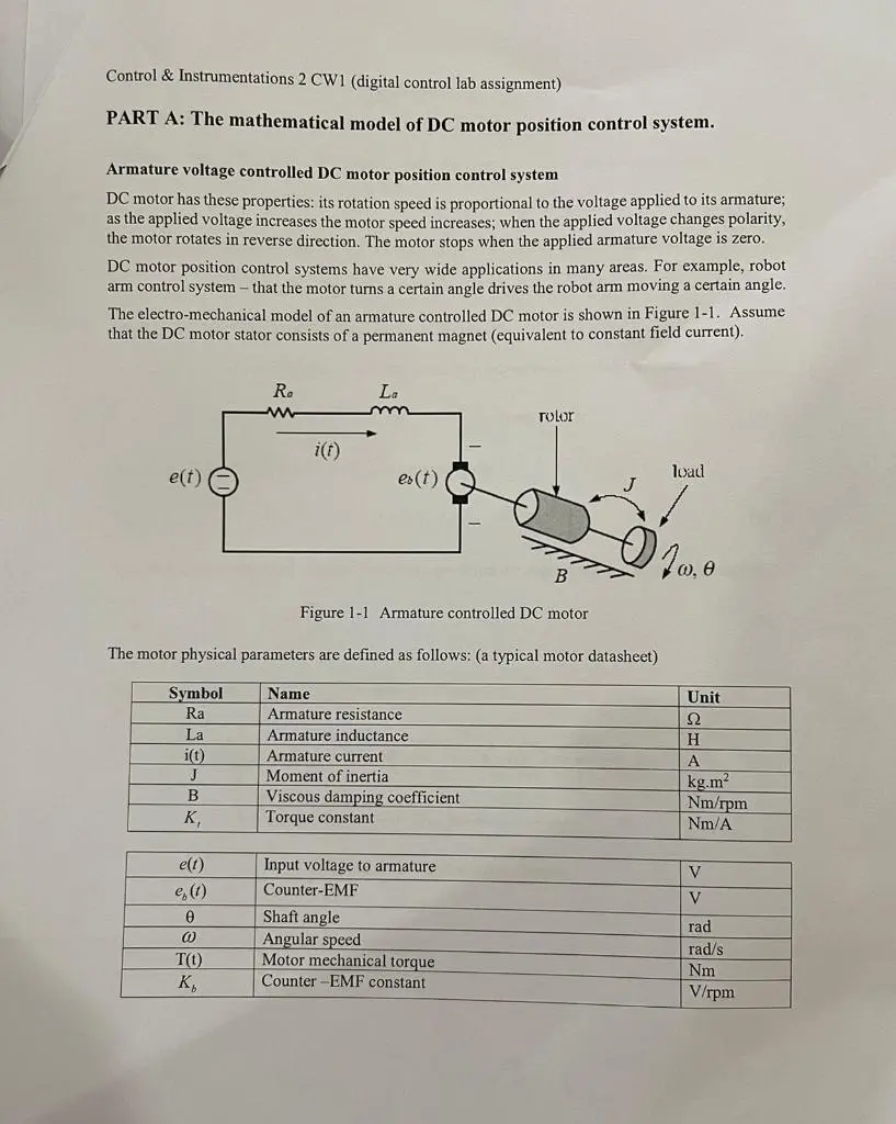
Transcribed Image Text:
Control & Instrumentations 2 CW1 (digital control lab assignment)
PART A: The mathematical model of DC motor position control system.
Armature voltage controlled DC motor position control system
DC motor has these properties: its rotation speed is proportional to the voltage applied to its armature;
as the applied voltage increases the motor speed increases; when the applied voltage changes polarity,
the motor rotates in reverse direction. The motor stops when the applied armature voltage is zero.
DC motor position control systems have very wide applications in many areas. For example, robot
arm control system - that the motor turns a certain angle drives the robot arm moving a certain angle.
The electro-mechanical model of an armature controlled DC motor is shown in Figure 1-1. Assume
that the DC motor stator consists of a permanent magnet (equivalent to constant field current).
Ra
www
La
m
rolor
e(t)
i(t)
ex(t)
-
B
Figure 1-1 Armature controlled DC motor
The motor physical parameters are defined as follows: (a typical motor datasheet)
Symbol
Name
Ra
Armature resistance
La
Armature inductance
i(t)
J
K₁
e(t)
e (1)
Ꮎ
@
T(t)
Ko
load
Unit
Ω
H
Armature current
Moment of inertia
Viscous damping coefficient
Torque constant
Input voltage to armature
Counter-EMF
Shaft angle
Angular speed
Motor mechanical torque
Counter-EMF constant
A
kg.m²
Nm/rpm
Nm/A
V
V
rad
rad/s
Nm
V/rpm
Control & Instrumentations 2 CW1 (digital control lab assignment)
The dynamics of the motor can be described by the following mathematic equations:
The motor torque, I(t), is linearly proportional the armature current. This is expressed as
T(t)=K,i(t)
Tess & ₤(5)
As the armature rotates, a counter EMF, proportional to the motor speed, is induced.
e,(t) = K, w(t)
Based on the Newton's Law, the torque balance equation is:
Mechanical torque - viscous friction = output torque = load torque
T()–Bo(t)=J
dw(t)
dt
←
Jdo(1)
dt
+ B w(t)=T(t)
Based on Kirchhoff's Law, the motor voltage equation is
di(t)
La
+Ra
i(t)= e(t)-e, (1)
dt
(1)
(2)
(3)
(4)
The relationship between the angular (rotation) speed and the angle position (angle displacement) is
de
dt
The block diagram of the DC motor as shown in Figure 1-2.
E(s)
I(s)
T(s)
Ω(s)
O(s)
G1
G2
G3
G4
E(s)
H1
Figure 1-2 DC motor block diagram
(5)
Control & Instrumentations 2 CW1 (digital control lab assignment)
Tasks: Complete questions 1-4 and write your solution in separate paper
Question 1:
Derive the transfer functions G1, G2, G3, G4 and H1 according to the signals indicated.
Redraw the motor block diagram and fill in the transfer functions with their respective expressions
that you have derived.
E(s)
I(s)
T(s)
Ω(5)
O(s)
Gl
G2
G3
G4
29
E(s)
HI
DC motor block diagram
Question 2:
Based on your completed Figure 1-2, determine the transfer function of the DC motor, where the
armature voltage is the input and the angular position is the output.
G,()-
©(s)
E(s)
Question 3:
Assume that the armature inductance (L.) is very small and can be neglected. Simplify your motor
transfer function to an equivalent second-order system
7 Hp Z
70
Ap (9) = (1-2). {5) 6, (s)--
[S+50
K
m
=
=
s(Ts+1)
70
5(5+507
And derive the expression of the motor gain constant K, and motor time constant T.
Ka
=
20
T =
Given that K=1.4 rpm/mV and T, = 0.02s, find the transfer function of the motor and write it in the
following form.
G₂(8)=
K/T
s(s+1/Tm)
m
70
5(5+50)
Control & Instrumentations 2 CW1 (digital control lab assignment)
Question 4:
The discrete-time control structure of the motor is shown in Figure 1-3, where the discrete-time model
for the plant (the motor) is Gμp (2), which is to be controlled by a discrete controller Gr(z). The
sampling period is T, = 2ms.
HP
GT (2)
C(z)
R(z)
G₁(2)
ZOH
G (5)
Figure 1-3
Closed-loop motor position control system
Using the motor transfer function obtained in Question 3 to determine the discrete-time model Gp (2)
for the motor (manual calculation).
G(2)-(1-2) 2G
GHP (2) (1-2) Z
Control & Instrumentations 2 CW1 (digital control lab assignment)
PART B: Design a digital controller for the DC motor position control system
using indirect design method.
Objectives:
To understand the system design specifications
To understand the discrete-time control system and digital compensator
To design a digital compensator for the motor position control system using indirect method
Use MATLAB to simulate the system and verify your design of the controller
Specifications for the motor control system performance
For this assignment, the desired specifications are as following. For a unit step input, the desired
closed-loop response should satisfy:
Settling time (2%) between 0.03 and 0.08 seconds,
• Overshoot no more than 25%
Zero steady state error.
Important note:
(30ms to 80ms)
(5%, 10%, 15%, 20%, 25%)
The settling time for c(k) can be 30, 40, 50, 60, 70 and 80ms.
The overshoot for y(k) can be 5%, 10%, 15%, 20%, 25%.
Each student has a set of different specifications. Ask you lab supervisor to assign you
the design specifications.
You will use the same parameters for the assignment part C.
Task of the project PART B
Design a controller (compensator) with the following given structure such that the closed-loop
position control system response satisfies the specifications that are assigned to you.
s+ zero
Ge(s)=kc
Bilinear transform
s+ pole
Your task is to determine the compensator parameters:
The compensator gain:
kc
(kz)
°
The compensator zero:
zero
(a)
•
The compensator pole:
pole
(b)
z+a
Ge(2)=k,
z+b
Control & Instrumentations 2 CW1 (digital control lab assignment)
Method of the compensator design
The indirect design method is to be used to determine the compensator parameters. Please read
through Chapter 5 of the C12 lecture notes for the details of this method.
Steps of the compensator design
1. Determine the desired damping ratio and natural frequency of the system based on the desired
performance specifications. Ask your Lecturer to know your specified Overshoot Mp and
settle time ts
2. Derive the closed-loop transfer function of the motor control system (with the compensator)
in the s-domain.
3. Let zero=1/T; namely let the compensator zero cancel the motor pole.
4. Compare the closed-loop characteristic equation with the desired characteristic equation to
determine the compensator parameters kc and pole (in the s-domain).
5. Choose the sampling period T, = 2ms which satisfies @, ≥ 20w,, T, ≤20T.
6. Apply Tustin's Bilinear Transformation transferring your designed compensator from s-
domain to z-domain.
2 z-1
T, z+1
=1000-1
z+1
In the z-domain, the compensator has the following form:
s+ zero
Ge(s)-kc
s+ pole
z+a
Bilinear transform
Ge(2)-k
z+b
7. Simulate your system and verify if all specifications are met. You can simulate in either ways
as shown in Figure 2-1.
R(z)
Compensator
G (2)
DC Motor
C(z)
ZOH
K
s(7+1)
Compensator
R(z)
Digitized DC Motor
C(z)
Ge(z)
G (2)
Figure 2-1 Motor with compensator
Control & Instrumentations 2 CW1 (digital control lab assignment)
Tasks: Answer questions 1-4 and write your answer in your Assignment answer:
Question 1:
Determine the desired damping ratio and natural frequency based the
specifications assigned to you
Mp=e
→ Damping ratio:
5=?
4
Natural frequency:
w₁ = ?
ζωη
The expected characteristic equation:
s²+25ws+w=0 is
(Eq1)
Question 2: Determine the compensator parameters in s-domain
The motor control system in the s-domain is shown in Figure 2-2.
R(s)
s + zero
KIT
C(s)
kc
s+ pole
s(s+1/T)
Open loop transfer function:
Figure 2-2 Motor control system in s-domain
Let zero=1/T,
zero=
Closed loop transfer function:
Closed loop characteristic equation:
Compare Eq2 with Eq1 to determine the required compensator parameters:
pole=
kc=
The required compensator transfer function is:
Ge(s)=ke
S+ zero
s+ pole
(Eq2)
Control & Instrumentations 2 CW1 (digital control lab assignment)
Question 3: Determine the digital compensator using Tustin's bilinear transformation
Set the sampling period T, = 2ms, and use Tustin's Bilinear Transformation to transfer your designed
compensator from s-domain to z-domain.
2 z-1
S=-
T₁ z+1
=1000-1
z+1
The digitalized controller transfer function G(z) is:
G₁(z)=
(Eq3)
Question 4: Simulate your final system and print out the results
Coniment on the simulation result on how the compensator has improved the
system's response.
b as
r an.
io
check_circle الجواب — حل مفصل خطوة بخطوة
hourglass_top
🔒
الحل الكامل متاح للمشتركين
اشترك في أرشيف الأسئلة لعرض هذا الحل وآلاف الحلول المفصلة خطوة بخطوة من معلمين معتمدين.