تم الحل ✓
categoryالهندسة الكهربائية
schoolبكالوريوس
event_available2026-07-15
السؤال
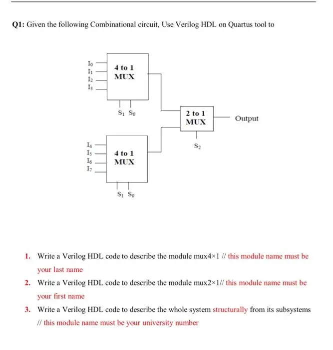
Transcribed Image Text:
Q1: Given the following Combinational circuit, Use Verilog HDL on Quartus tool to
13
4 to 1
MUX
S₁ So
2 to 1
MUX
Output
1337
14
Is
4 to 1
16
MUX
S₁ So
1. Write a Verilog HDL code to describe the module mux4×1 // this module name must be
your last name
2. Write a Verilog HDL code to describe the module mux2×1// this module name must be
your first name
3. Write a Verilog HDL code to describe the whole system structurally from its subsystems
// this module name must be your university number
Q2:
Problem: Design and Simulation of 8-bit ALU
Design an 8-bit ALU circuit that receives two 8-bit input numbers X [7:0] and Y [7:0], and produces a
8-bit output z[7:01, an output carry Cout, an overflow flag Ov, and Zero flag. The circuit
implements the following 12 functions based on a 3-bit control input C [3:0]:
Function
Addition: Z-X+Y
Subtraction: Z-X-Y
Reminder: Z=X&Y
Bitwise AND: Z=X&Y
Code
000
001
010
011
100
101
Bitwise OR: Z-XIY
Concatenate: Z-(X[3:0]
Y[3:0])
110
Equality: Zero-XY
111
Less than: Cout-X<Y
Notes:
a) Show the block diagram design of your 8-bit ALU using components like Adder,
Multiplexor, etc. as needed.
b) Model each component separately. You should have different modules for the adder,
multiplexer, etc.
c) Write a Verilog test scenarios to test both the 8-bit ALU. Verify the correctness by simulation.
d) Show snapshots of all simulation waveforms.
e) Submit a report (Word or PDF document) should contain Problem description, the block diagram,
a copy of the Verilog modules and the waveforms taken directly as snapshots from the simulator.
In addition to building the Quartus project, you need to write down one report for each student
that includes the following items:
check_circle الجواب — حل مفصل خطوة بخطوة
hourglass_top
🔒
الحل الكامل متاح للمشتركين
اشترك في أرشيف الأسئلة لعرض هذا الحل وآلاف الحلول المفصلة خطوة بخطوة من معلمين معتمدين.