تم الحل ✓
categoryالهندسة الكهربائية
schoolبكالوريوس
event_available2026-07-15
السؤال
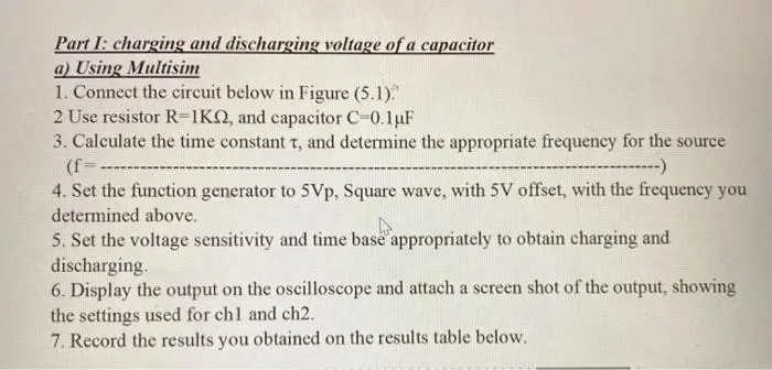
Transcribed Image Text:
Part I: charging and discharging voltage of a capacitor
a) Using Multisim
1. Connect the circuit below in Figure (5.1).
2 Use resistor R-1K, and capacitor C-0.1uF
3. Calculate the time constant t, and determine the appropriate frequency for the source
(f=.
-------------)
4. Set the function generator to 5Vp, Square wave, with 5V offset, with the frequency you
determined above.
5. Set the voltage sensitivity and time base appropriately to obtain charging and
discharging.
6. Display the output on the oscilloscope and attach a screen shot of the output, showing
the settings used for chl and ch2.
7. Record the results you obtained on the results table below.
F.G
V1
C1
Figure 5.1
*Note that T = R C lk 0.lu 0.1 m sec so, we use a clock source with frequency-
=
10r
10-0.1m
1kHz
Time (sec)
Charging
Voltages from Simulation
Calculated voltages
Vch Vs (1-e (-/RC))
0.1
0.2
0.3
0.4
0.5
Discharging
0.6
0.7
0.8
0.9
1.0
Table 5.1
*Screen shot of the output displayed on the oscilloscope:
VDis Vse (URC)
Conclusions:
check_circle الجواب — حل مفصل خطوة بخطوة
hourglass_top
🔒
الحل الكامل متاح للمشتركين
اشترك في أرشيف الأسئلة لعرض هذا الحل وآلاف الحلول المفصلة خطوة بخطوة من معلمين معتمدين.