تم الحل ✓
categoryهندسة كهربائية
schoolبكالوريوس
event_available2026-07-15
السؤال
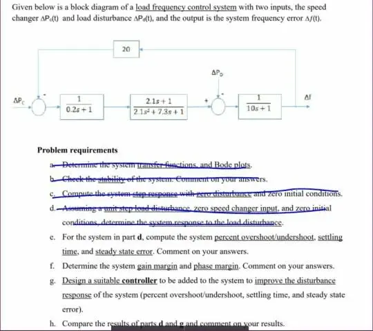
Transcribed Image Text:
Given below is a block diagram of a load frequency control system with two inputs, the speed
changer AP.(t) and load disturbance AP(t), and the output is the system frequency error A/(t).
20
ΔΡ
1
2.1s+1
0.2s+1
2.1s+7.3s+1
AP
10s+1
Problem requirements
a Determine the system transfer functions, and Bode plots.
b Cheek the stability of the system. Comment on your answers.
c. Compute the system step response with pero disturbance and zero initial conditions.
d. Assuming a unit step fond disturbance. zero speed changer input, and zero initial
conditions determine the system response to the load disturbance.
e. For the system in part d, compute the system percent overshoot/undershoot. settling
time, and steady state error. Comment on your answers.
f. Determine the system gain margin and phase margin. Comment on your answers.
g. Design a suitable controller to be added to the system to improve the disturbance
response of the system (percent overshoot/undershoot, settling time, and steady state
error).
h. Compare the results of parts d and g and comment on your results.
check_circle الجواب — حل مفصل خطوة بخطوة
hourglass_top
🔒
الحل الكامل متاح للمشتركين
اشترك في أرشيف الأسئلة لعرض هذا الحل وآلاف الحلول المفصلة خطوة بخطوة من معلمين معتمدين.