تم الحل ✓
categoryالهندسة الكهربائية
schoolبكالوريوس
event_available2026-07-15
السؤال
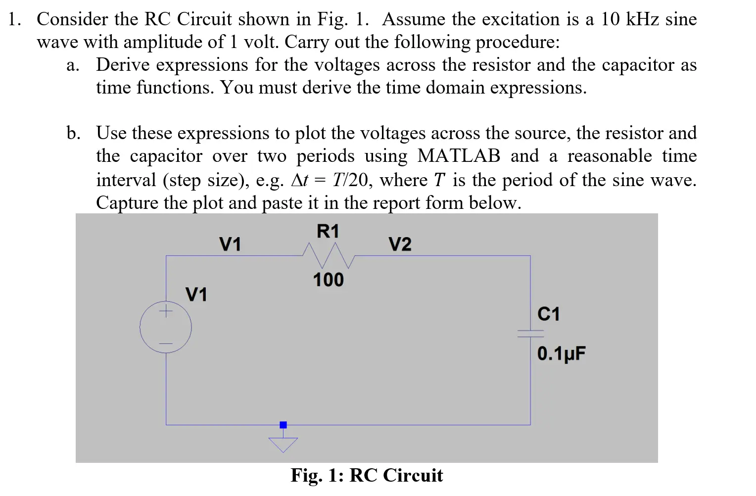
Transcribed Image Text:
1. Consider the RC Circuit shown in Fig. 1. Assume the excitation is a 10 kHz sine
wave with amplitude of 1 volt. Carry out the following procedure:
a.
Derive expressions for the voltages across the resistor and the capacitor as
time functions. You must derive the time domain expressions.
b. Use these expressions to plot the voltages across the source, the resistor and
the capacitor over two periods using MATLAB and a reasonable time
interval (step size), e.g. At = T/20, where T is the period of the sine wave.
Capture the plot and paste it in the report form below.
V1
R1
V1
V2
100
Fig. 1: RC Circuit
C1
0.1μF
check_circle الجواب — حل مفصل خطوة بخطوة
hourglass_top
🔒
الحل الكامل متاح للمشتركين
اشترك في أرشيف الأسئلة لعرض هذا الحل وآلاف الحلول المفصلة خطوة بخطوة من معلمين معتمدين.