تم الحل ✓
categoryالهندسة الميكانيكية
schoolبكالوريوس
event_available2026-07-15
السؤال
Transcribed Image Text:
System description:
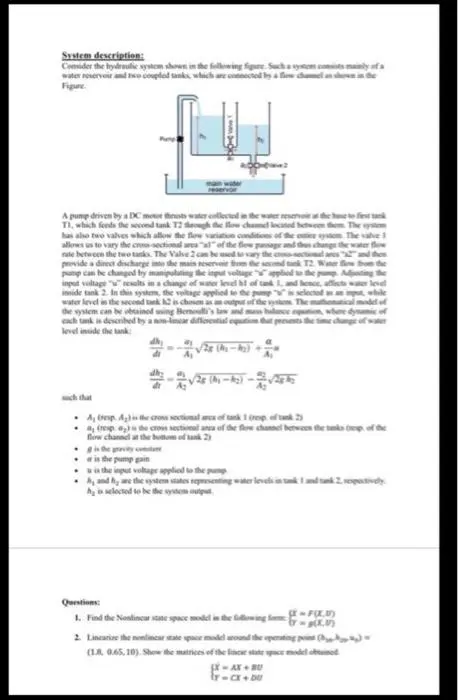
Consider the hydraulic system shown in the following figure. Such a system consists mainly fa
water reservoir and two coupled tanks, which are c
Figure
A pump driven by a DC motor thrusts water collected in the water reservoir at the hue to first tak
TI, which feeds the second tank T2 though the flow channel located between them. The system
has also two valves which allow the flow variation conditions of the esties system. The valve 1
allows us to vary the cross-sectional arca "al" of the flow passage and des change the water fl
rate between the two tanks. The Valve 2 can be used to vary the c-sectional
and the
provide a direct discharge into the main reservoir from the second tank 12. Water flow from the
pump can be changed by manipulating the input voltage applied to the pump Acing the
input voltage "" results in a change of water level ht of tank 1, and hence, affects water level
inside tank 2. In this system, the voltage applied to the pump" selected as an input, while
water level in the second tank 12 is chosen as an output of the system. The mathematical model of
the system can be obtained using Bernoulli's law and mass b
where dynamic of
each tank is described by a non-linear differential equation t
level inside the tank
presents the time change of water
such that
(-)-
Amp. A) is the cross sectional area of tank 1 (rep of tank 2)
(resp) is the cross sectional area of the flow channel between the tanks t
Bow channel at the bottom of tank 2)
is the pump gain
is the input voltage applied to the pump
h, and hy are the system states representing water levels
hy is selected to be the system output
Questions:
1. Find the Nonlinear state space model in the following form
-F(X5)
2. Linearize the nonlinear state space model around the operating point (33
(1.8, 0.65,10). Show the matrices of the lines state space model obtained
SX-AX + BU
r-CX+DU
System description:
Consider the hydraulic system shown in the following figure. Such a system consists mainly of a
water reservoir and two coupled tanks, which are connected by a flow channel as shown in the
Figure.
Pump
main water
reservoir
A pump driven by a DC motor thrusts water collected in the water reservoir at the base to first tank
TI, which feeds the second tank T2 through the flow channel located between them. The system
has also two valves which allow the flow variation conditions of the entire system. The valve 1
allows us to vary the cross-sectional area "al" of the flow passage and thus change the water flow
rate between the two tanks. The Valve 2 can be used to vary the cross-sectional area "a2" and then
provide a direct discharge into the main reservoir from the second tank T2. Water flow from the
pump can be changed by manipulating the input voltage "u" applied to the pump. Adjusting the
input voltage "u" results in a change of water level hl of tank 1, and hence, affects water level
inside tank 2. In this system, the voltage applied to the pump "u" is selected as an input, while
water level in the second tank h2 is chosen as an output of the system. The mathematical model of
the system can be obtained using Bernoulli's law and mass balance equation, where dynamic of
each tank is described by a non-linear differential equation that presents the time change of water
level inside the tank:
dhy
dt
α
1-
Ai
dh
di
a
A₂
√28 (-)-28
Az
such that
⚫A, (resp. A₂) is the cross sectional area of tank 1 (resp. of tank 2)
⚫a, (resp. a) is the cross sectional area of the flow channel between the tanks (resp. of the
flow channel at the bottom of tank 2)
⚫g is the gravity constant
a is the pump gain
u is the input voltage applied to the pump.
h, and h₂ are the system states representing water levels in tank 1 and tank 2, respectively.
hy is selected to be the system output.
Questions:
1. Find the Nonlinear state space model in the following form: FOXU)
y= g(x,U)
2. Linearize the nonlinear state space model around the operating point (hh20-440) =
(1.8, 0.65, 10). Show the matrices of the linear state space model obtained
(X = AX + BU
ly=CX + DU
check_circle الجواب — حل مفصل خطوة بخطوة
hourglass_top
🔒
الحل الكامل متاح للمشتركين
اشترك في أرشيف الأسئلة لعرض هذا الحل وآلاف الحلول المفصلة خطوة بخطوة من معلمين معتمدين.