تم الحل ✓
categoryالهندسة الكهربائية
schoolبكالوريوس
event_available2026-07-15
السؤال
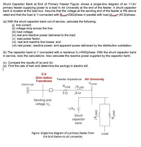
Transcribed Image Text:
Shunt Capacitor Bank at End of Primary Feeder Figure: shows a single-line diagram of an 11-kV
primary feeder supplying power to a load in Air University at the end of the feeder. A shunt capacitor
bank is located at the load bus. Assume that the voltage at the sending end of the feeder is 5% above
rated and that the load is Y-connected with B-2002/phase in parallel with load iXoad=j40 n/phase.
(a) With the shunt capacitor bank out of service, calculate the following:
(i) line current;
(ii) voltage drop across the line;
(iii) load voltage:
(iv) real and reactive power delivered to the load;
(v) load power factor;
(vi) real and reactive line losses; and
(vii) real power, reactive power, and apparent power delivered by the distribution substation.
(b) The capacitor bank is Y connected with a reactance Xc=402/phase. With the shunt capacitor bank
in service, redo the calculations. Also calculate the reactive power supplied by the capacitor bank.
(c) Compare the results of (a) and (b).
(e) Find the rate of kwh and determine the savings in electric bill.
E-9
Grid station
Transforme
Feeder impedance Air University
VLOAD
137/11 kV
RLINE
JXLINE
m
w
312
16.02
Sending end
voltage Vs
-Xc
T
Shunt
capacitor
bank
jXLOAD
Figure: Single-line diagram of a primary feeder from Load
E-9 Grid Station to Air University
ww
RLOAD
check_circle الجواب — حل مفصل خطوة بخطوة
hourglass_top
🔒
الحل الكامل متاح للمشتركين
اشترك في أرشيف الأسئلة لعرض هذا الحل وآلاف الحلول المفصلة خطوة بخطوة من معلمين معتمدين.