تم الحل ✓
categoryالهندسة الكهربائية
schoolبكالوريوس
event_available2026-07-15
السؤال
Transcribed Image Text:
BUCK-BOOST CONVERTER
PROCEDURE
SECTION A: PRE-LAB CALCULATION
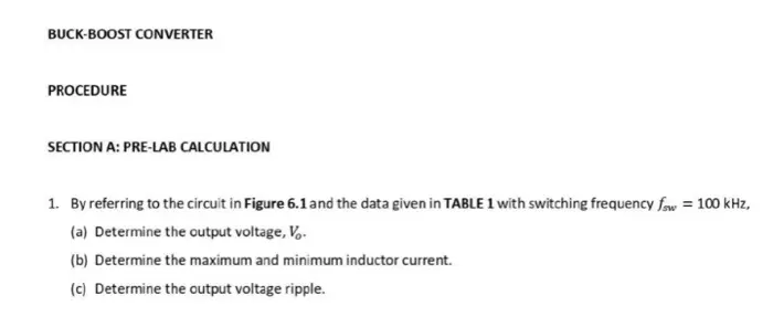
1. By referring to the circuit in Figure 6.1 and the data given in TABLE 1 with switching frequency fsw=100 kHz,
(a) Determine the output voltage, Vo.
(b) Determine the maximum and minimum inductor current.
(c) Determine the output voltage ripple.
Vs
JZ
m
VL
Figure 6.1: BUCK-BOOST Converter
www.
Vout
Parameter name
Symbol
Value
Input voltage
V₁
20 V
Output Capacitor
C
50 μF
Inductor
L
20 KH
Load resistance
R
10Q
Duty Cycle
D
0.4
Duty cycle, D
Table 2b: Variation in duty cycle, D
Output voltage, V
0.4
0.5
0.6
PROBLEMS
1. Briefly describe the operation of the BUCK Converter, BOOST Converter and BUCK-BOOST Converter.
2. What is the effect of varying the duty cycle, D to the output voltage waveform, V in BUCK-BOOST Converter?
3. Why there is a discrepancy between the calculation and the simulation results?
check_circle الجواب — حل مفصل خطوة بخطوة
hourglass_top
🔒
الحل الكامل متاح للمشتركين
اشترك في أرشيف الأسئلة لعرض هذا الحل وآلاف الحلول المفصلة خطوة بخطوة من معلمين معتمدين.