تم الحل ✓
categoryالفيزياء
schoolبكالوريوس
event_available2026-07-15
السؤال
Transcribed Image Text:
Introduction
Light exhibits a wave-particle duality where both a wave and particle model can describe many
observations in optics. In this experiment you will now be examining the wave-like properties of
light.
Theory
Light as a wave - diffraction from a single/double slit
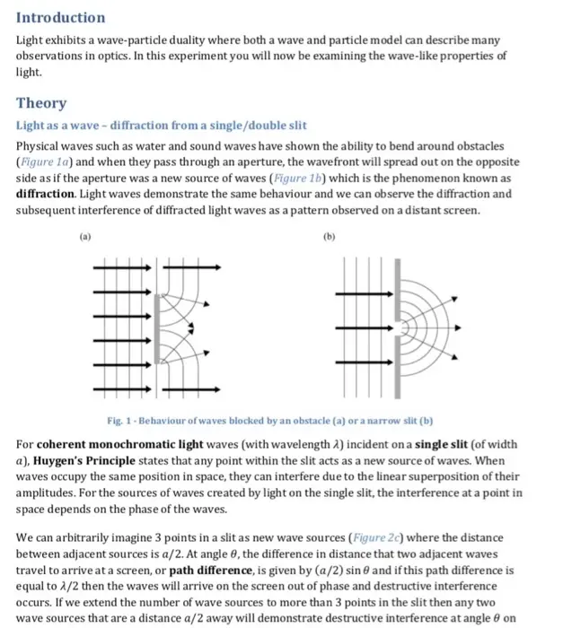
Physical waves such as water and sound waves have shown the ability to bend around obstacles
(Figure 1a) and when they pass through an aperture, the wavefront will spread out on the opposite
side as if the aperture was a new source of waves (Figure 1b) which is the phenomenon known as
diffraction. Light waves demonstrate the same behaviour and we can observe the diffraction and
subsequent interference of diffracted light waves as a pattern observed on a distant screen.
(a)
(b)
| | | | | |
Fig. 1-Behaviour of waves blocked by an obstacle (a) or a narrow slit (b)
For coherent monochromatic light waves (with wavelength 2) incident on a single slit (of width
a), Huygen's Principle states that any point within the slit acts as a new source of waves. When
waves occupy the same position in space, they can interfere due to the linear superposition of their
amplitudes. For the sources of waves created by light on the single slit, the interference at a point in
space depends on the phase of the waves.
We can arbitrarily imagine 3 points in a slit as new wave sources (Figure 2c) where the distance
between adjacent sources is a/2. At angle 0, the difference in distance that two adjacent waves
travel to arrive at a screen, or path difference, is given by (a/2) sin and if this path difference is
equal to 2/2 then the waves will arrive on the screen out of phase and destructive interference
occurs. If we extend the number of wave sources to more than 3 points in the slit then any two
wave sources that are a distance a/2 away will demonstrate destructive interference at angle on
If two slits (double-slit) are used instead of one, the diffraction pattern due to the single-slit effect
is still noticeable on a screen (grey pattern of Figure 2b) but additional regions of alternating bright
and dark spots appear within the broad maxima (red dotted lines in Figure 2b). These interference
fringes are the result of the second slit which acts as a secondary sources of wavefronts. At any
point on the screen, the path lengths for the light from either slit is unequal except at the center of
the screen. We can calculate regions of constructive and destructive interference for a path
difference of d sin (Figure 2d). The angle to the intensity maximum (bright fringes) occurs when
the path difference is an integer multiple of the light's wavelength:
d sine mλ (m = 0,1,2,...)
where is the angle to the mth maximum (0 is the central, 1 is the first maximum to one side, 2 is
the second maximum to the same side, etc...). We can again use the small angle approximation to
find the distance between slits d by measuring the distance between bright interference fringes y
and the distance from double-slit to the screen D:
d=
MAD
(m = 0, 1, 2,...)
Diffraction grating
Diffraction gratings are used to make very accurate measurements of the wavelength of light. In
theory, they function similarly to a two slit aperture but a diffraction grating has many slits, rather
than two, and the slits are very closely spaced. By using closely spaced slits, the regions of
constructive interference will spread to larger angles and these spacings can be measured more
accurately. However, when the light is spread to large angles, brightness is lost therefore a grating
uses many slit to provide many sources of light to preserve brightness.
The narrow apertures in a diffraction grating are separated by an equal distance d. Similar to
double-slit interference, if the path difference for waves from two apertures is an integer multiple
of then there will be constructive interference and a bright region on your screen:
d sin = mλ (m = 0,1,2...)
Polarization
A linear absorbing polarizer only allows light which has electric field vibrating in a particular plane
(known as the polarizer's axis) to pass through it. Unpolarized light has an electric field that
vibrates in all planes perpendicular to the direction of propagation and if unpolarized light is
incident upon an ideal polarizer, 50% of the light will be transmitted. However, in practice no
polarizer is ideal therefore less than 50% of the light is usually transmitted.
The transmitted light becomes polarized in the axis of the polarizer and if this now-polarized light
is incident upon a second polarizer (sometimes called an analyzer), the intensity of light
transmitted will depend on the difference in angles of the polarization axes of the two polarizers.
This is because some component E of the electric field of the polarized light will lie in the same
direction as the axis of the second polarizer (Figure 3). For an initial electric field component Eo, we
have E=E, cos p where op is the angle between the polarization axes of the two polarizing filters.
the screen and there will be an overall dark spot, or dark fringe, representing a minimum in light
intensity occurring at that position on the screen. At other angles there is a combination of
destructive and constructive interference and wide fringes of varying brightness will occur
between the dark fringes in the diffraction pattern of the single slit (Figure 2a). The equation to
locate the minima in light intensity is given by:
a sin = mλ (m = 1,2,3,...)
where is the angle to the mth minimum which represents the order (1 is 1st minimum, 2 is 2nd
minimum, etc...), counting from the centre outwards. Since the angles are small we can use the
small angle approximation (sin tany/D) where y is the distance between adjacent minima
on the screen and D is the distance from the slit to the screen (Figure 2a, 2c). The diffraction
equation can be solved to find the slit width a:
(a)
mλD
a=-
(m = 1,2,3...)
(b)
(c)
slit
m-1
m-2
slits
(d)
Fig. 2 -(a) The single slit diffraction pattern (b) Diffraction pattern and interference fringes from a double slit
(c) Diffraction geometry for a single slit (d) Diffraction and interference geometry for a double slit
The intensity of light varies as the square of the electric field so the transmitted light intensity
through the second filter is given by Malus' law:
1 = 10 cos² Q
where lo is the intensity of the light passing through the first filter. Intensity of light, which is
sometimes called irradiance, is measured in units of radiant flux (power) per unit area (W/m²). A
similar measurement for light sources that is proportional to intensity is called illuminance which
measures the luminous flux per unit area (lumens/m² also known as lux).
The two extreme cases illustrated by Malus' law show that for p = 0, the intensity is maximum
(I = 10) since the two polarization axes are aligned. And if the two polarizers have axes
perpendicular to each other then = 90° and the transmitted light is 0.
polarizing
axis
incident
unpolarized
light
(transmitted)
polarizing
axis
polarizer
polarizer
Fig. 3-Setup for transmission of light through two linear absorbing polarizers
3) Polarization of light
The last part of the experiment is to look at how polarizers are used to filter and attenuate light.
You build the same experimental setup that is shown in Figure 3 of the lab manual. A beam of
unpolarized white light goes through two linear polarizers and is then incident on a light detector
that measures illuminance or illumination (in units of lux). You set the first polarizer's axis to be
vertical and carefully rotate the second polarizer with respect to the first and measure the signal
from the light detector. You record the difference in the angles (in °) of the polarizer's axes as well
as the measured illumination in the data file polarization.csv.
A photograph of your setup is shown in Figure 3.
white
light
sensor
light polarizer1
polarizer 2
Fig. 3 - Setup for polarization of light experiment
A
123
1 Angle (degrees)
B
Illumination (lux)
90
0
3
105
5.698394775
4
120
18.66958618
5
135
37.12768555
6
150
54.01138306
7
165
65.3024292
8
180
67.38204956
9
195
60.72021484
10
210
46.48010254
11
225
28.95019531
12
240
12.20748901
13
255
1.84463501
14
270
0
15
285
3.842010498
16
300
16.95419312
17
315
34.44885254
18
330
51.5675354
19
345
63.6340332
20
360
67.32330322
21
15
61.47216797
22
30
47.53753662
23
45
29.36141968
24
60
12.10174561
25
75
1.022186279
26
90
3) Polarization of light 6 pts
Graph 1: 3 pts
Using the data from the file polarization.csv, plot a graph of the illumination vs. cos² for the
white light passing through the two polarizing filters. Show a linear regression of the data including
the uncertainties on the fitting parameters. You should also show your data table in your graph file.
Question 3: 2 pts
From your graph, what is the maximum illumination of light. Compare this value with the maximum
value of illumination that you measured and recorded in the data file polarization.csv. Do the values
agree with each other? Can you explain why one value is higher than the other. Are the results of
the experiment consistent with Malus's law?
Calculation 3: 1 pts
Using the equation of the linear regression from your graph, calculate the illumination for p = 0°
and compare it (using a % difference calculation) to the measured value of illumination at that
angle (no need for uncertainty calculation). Do the values agree with each other? What does this tell
us about the y-intercept?
check_circle الجواب — حل مفصل خطوة بخطوة
hourglass_top
🔒
الحل الكامل متاح للمشتركين
اشترك في أرشيف الأسئلة لعرض هذا الحل وآلاف الحلول المفصلة خطوة بخطوة من معلمين معتمدين.