تم الحل ✓
categoryالهندسة الكهربائية
schoolبكالوريوس
event_available2026-07-15
السؤال
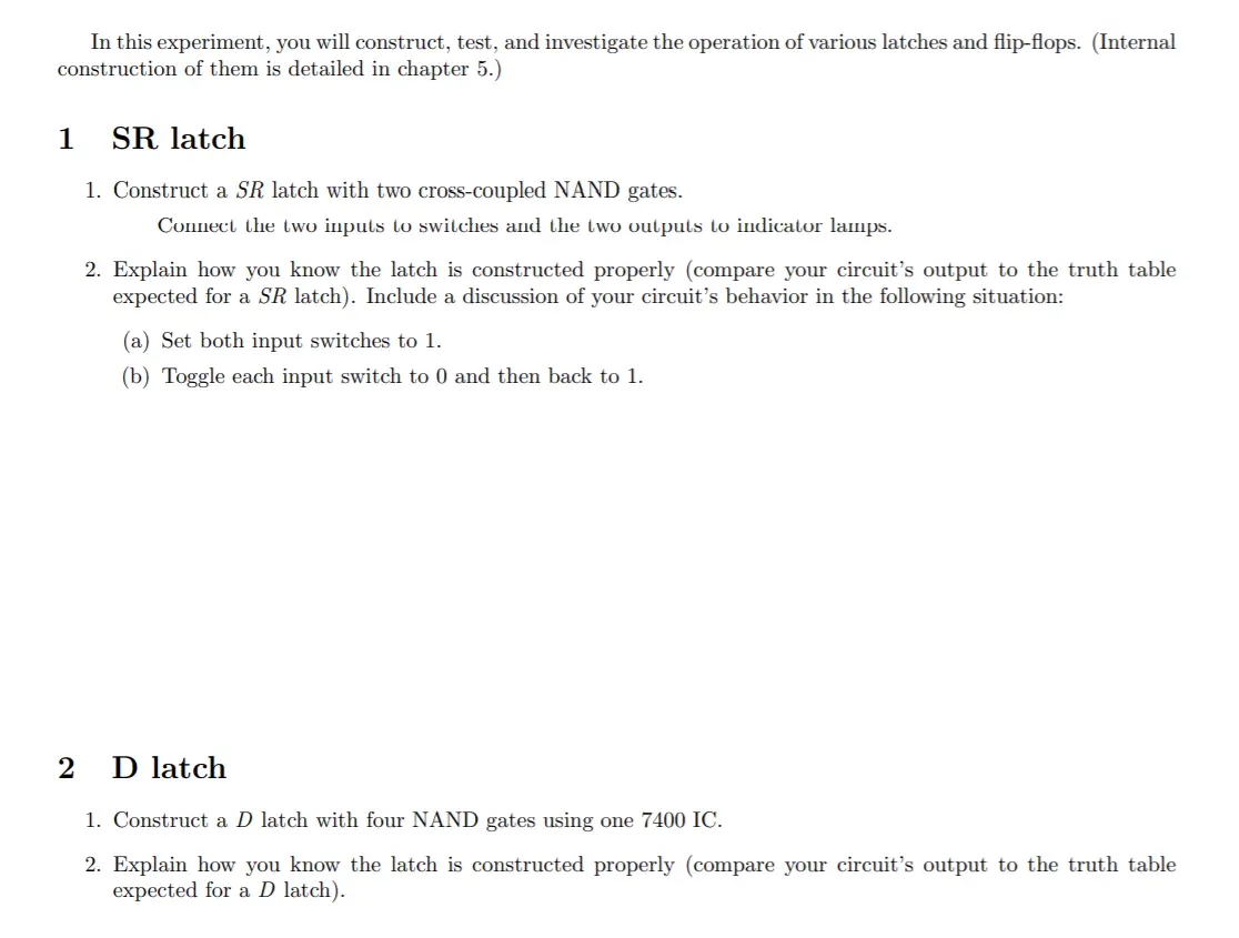
Transcribed Image Text:
In this experiment, you will construct, test, and investigate the operation of various latches and flip-flops. (Internal
construction of them is detailed in chapter 5.)
1
SR latch
1. Construct a SR latch with two cross-coupled NAND gates.
Connect the two inputs to switches and the two outputs to indicator lamps.
2. Explain how you know the latch is constructed properly (compare your circuit's output to the truth table
expected for a SR latch). Include a discussion of your circuit's behavior in the following situation:
(a) Set both input switches to 1.
(b) Toggle each input switch to 0 and then back to 1.
2
D latch
1. Construct a D latch with four NAND gates using one 7400 IC.
2. Explain how you know the latch is constructed properly (compare your circuit's output to the truth table
expected for a D latch).
3
Primary-secondary Flip-flop
1. Construct a primary-secondary D flip-flop using two D latches and an inverter.
Connect the D input to a switch and the flip-flop's clock input to a pulse button.
Connect the output of the primary latch to one lamp and the output of the secondary latch to another.
Set the value of the input to the complement output.
2. Press the pulse button, keeping track of the four parts press, hold, release, hold of the pulse cycle, a few
times while observing the indicator lamps.
3. Explain how you know the flip-flop is constructed properly based on your observations.
4 Edge-Triggered Flip-flop
1. Construct a D-type positive edge-triggered flip-flop using six NAND gates.
(a) Connect the flip-flop's clock input to one of the pulse buttons.
(b) Connect the D input to a toggle switch.
(c) Connect output Q to an LED lamp.
(d) Set the value of D to the complement of Q (using the toggle switch).
(e) Take a photo of your wired gate-level D-type flip-flop.
(f) Record observations of the operation of the flip-flop in order to demonstrate that the flip-flop output
changes only in response to a positive transition of the clock pulse. Verify that the output does NOT
change when
the clock input is logic 1, or
⚫ when the clock goes through a negative transition, or
when the clock input is logic 0.
5
IC Flip-flops
IC type 7476 consists of two JK-type positive edge-triggered flip-flops with preset and clear. The pin assignment
and function table are shown below.
Figure 1: IC 7476 pin diagram and function table
2
7
4
PR
15
9
PR
11
J
Q
J
e
6
CK
CK
Vcc = pin 5
GND = pin 13
16
14
12
10
K Q'
K Q'
CLR
CLR
3
8
Function table
Inputs
Outputs
Preset Clear Clock
J
K
Q
Q'
100
010
X
X
X
XXX
X
X
X
101
0
1
1
1
1
1
1
1
1
1
1
0
0
No change
011
1
0
1
0
1
0
1
Toggle
1. Construct a circuit that implements one of the JK flip-flops in the 7476.
(a) Explain how you know the flip-flop is wired properly.
(b) Take a photo of your wired 7476 flip-flop circuit.
6 Deliverables
your explanations for sections 1, 2, and 5
your photos for sections 4 and 5
⚫ your observations for section 5 demonstrating the required operation
3. Derive the state table and the state diagram of the sequential circuit shown. Explain the function that the
circuit performs.
A'
A
B'
B
Clk
Clk
T
T
Clock
check_circle الجواب — حل مفصل خطوة بخطوة
hourglass_top
🔒
الحل الكامل متاح للمشتركين
اشترك في أرشيف الأسئلة لعرض هذا الحل وآلاف الحلول المفصلة خطوة بخطوة من معلمين معتمدين.