تم الحل ✓
categoryالهندسة الميكانيكية
schoolبكالوريوس
event_available2026-07-15
السؤال
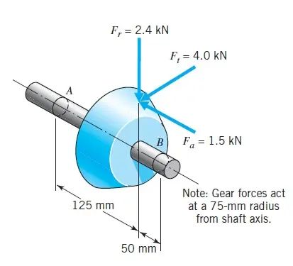
Transcribed Image Text:
A
F,= 2.4 KN
F₁ = 4.0 kN
125 mm
50 mm
B
F = 1.5 kN
Note: Gear forces act
at a 75-mm radius
from shaft axis.
Problems
17.26
17.27
741
and the axial force loading. (The desired diagrams include the seven shown in
Figure 17.7c. Add a similar diagram showing axial load, with tension plotted
positive and compression negative.)
(b) What radial and thrust loads are applied to the bearings?
(c) identify the most critically loaded shaft cross section, and for this location
shaft will be machined from steel having 5,150 ksi and S, 120 ksi, and
determine the diameter theoretically required for infinite life. Assume that the
that Ky 2.0, 1.5, and 2.0 will apply to bending, torsional, and axial loading.
respectively, at the critical location.
[Ans: (b) 233 lb radial to A: 754 lb radial and 400-lb thrust to B, (c) just to the
right of the gear, approximately 0.94 in.]
A stepped steel shaft (as shown in Chapter 4, Figure 4.35) has Dld 1.2.d=30 mm,
and r3 mm. The surfaces are machined and the steel has a hardness of 200 Bhn
and strength values of S, 700 MPa and S, 550 MPa. The rotating steel shaft used
in a spur gear reducer is subjected to a constant bending moment and a steady torque
However, these are nominal values and do not take into account stress concentration
which results in calculated stresses of 60 MPa bending and 80 MPa torsion.
caused by the stepped shaft (shoulder). The fatigue stress concentration caused by
the shoulder of this steel shaft is Ky=1.53 for bending and Ke-1.28 for torsion. The
modified endurance limit is 239 MPa. Determine the safety factor with respect to
infinite fatigue life.
A bevel pinion and shaft are shown in Figure P17.27. Bearing A takes thrust. The left
end of the shaft is coupled to an electric motor, and the right end is free. Load com-
ponents applied by the mating bevel gear are shown.
(a) Draw load, shear force, and bending moment diagrams for the shaft in both hor
izontal and vertical planes, plus torsional-load and axial-load diagrams. (The
desired diagrams include the seven shown in Figure 17.7c plus a similar dia-
gram for axial loads, with tension plotted as positive.)
(b) Determine the radial and
thrust loads applied to the
two bearings.
(c) Identify the critically loaded
shaft cross section and esti-
mate the safety factor with
respect to eventual fatigue
failure using the following
data: shaft diameter = 33 mm,
===
K 1.3, 1.2, and 1.3 for
bending, torsional, and axial
loading, respectively; mater-
ial is steel with S₁ = 900
MPa and Sy 700 MPa:
and critical surfaces have a
ground finish.
=
F,= 2.4 KN
F, 4.0 KN
125 mm
F-1.5 kN
Note: Gear forces act
at a 75-mm radius
from shaft axis.
50 mm
FIGURE P17.27
Beman
17.28D Figure P17.28D shows two alternative approaches to the problem of supporting an
overhung or cantilevered chain idler sprocket (or spur gear or belt sheave). What fun-
damental differences are there between the two with respect to shaft loading and
bearing loading? How would the comparison change if a bevel gear were substituted
for the chain sprocket?
check_circle الجواب — حل مفصل خطوة بخطوة
hourglass_top
🔒
الحل الكامل متاح للمشتركين
اشترك في أرشيف الأسئلة لعرض هذا الحل وآلاف الحلول المفصلة خطوة بخطوة من معلمين معتمدين.