تم الحل ✓
categoryالهندسة الكهربائية
schoolبكالوريوس
event_available2026-07-15
السؤال
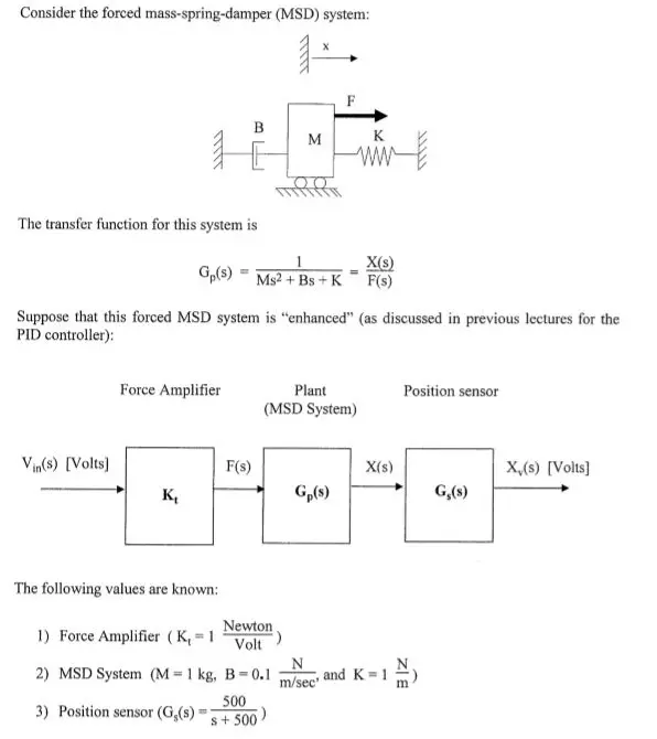
Transcribed Image Text:
Consider the forced mass-spring-damper (MSD) system:
mir
1
M
F
K
www
The transfer function for this system is
X(s)
Gp(s) = Ms²+Bs+K F(s)
Suppose that this forced MSD system is "enhanced" (as discussed in previous lectures for the
PID controller):
Force Amplifier
Plant
(MSD System)
Position sensor
Vin(s) [Volts]
F(s)
X(s)
X₁(s) [Volts]
K₁
Gp(s)
G,(s)
The following values are known:
Newton
1) Force Amplifier (K₁ = 1
Volt
2) MSD System (M=1 kg, B=0.1
3) Position sensor (G,(s)
500
S+500
and K-1
m/sec'
ZIE
Part a) Sketch completely the Bode plots of the transfer function of the OVERALL system:
(16 points)
X₁(s)
1
G(s) Vin(s) K₁ Gp(s) G₁(s) =
500
+ (0.1)s+1s+500
You must provide some explanation for these Bode plots (i.e. do not just sloppily draw them
without written explanation).
Phase (degrees)
Magnitude (dB)
-50
-100
-150
-200
50
0
-50
-100
-150
Bode plots for G(s) - Question (Part a)
-200
-250
2
10
101
10°
10'
10²
Frequency (rad/sec)
D
10³
10'
10³
-250
-300
102
101
10°
10'
10²
10³
10
105
Frequency (rad/sec)
Part b) Now consider the following transfer function:
(7 points)
-500
H(s)-
+ (0.1)s+1'
+500
Note that this "H(s)" is equal to (-1)*G(s) from "Part a." This system could represent the
same system as from "Part a," but with the reverse polarity of the position sensor output voltage.
Describe how the Bode plots (magnitude, phase) for this "H(s)" would compare with the Bode
plots for "G(s)" from "Part a."
Note that you do NOT need to draw/sketch Bode plots for this part, but you need to explain your
answer clearly (perhaps with "some" calculations?).
HINT: You can view this new transfer function as
H(s)=
500
+ (0.1)s+1
+500)(-1).
check_circle الجواب — حل مفصل خطوة بخطوة
hourglass_top
🔒
الحل الكامل متاح للمشتركين
اشترك في أرشيف الأسئلة لعرض هذا الحل وآلاف الحلول المفصلة خطوة بخطوة من معلمين معتمدين.