تم الحل ✓
categoryهندسة كهربائية
schoolبكالوريوس
event_available2026-07-15
السؤال
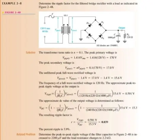
Transcribed Image Text:
EXAMPLE 2-8
FIGURE 2-48
Determine the ripple factor for the filtered bridge rectifier with a load as indicated in
Figure 2-48.
120 V
60Hz
10:1
Dy
1000F
All diodes are 1N4001,
Output
w
2200
Solution The transformer turns ratio is n = 0.1. The peak primary voltage is
Vi 1.414V 1.414(120 V) - 170 V
The peak secondary voltage is
VV-0.1(170 V) - 17.0V
The unfiltered peak full-wave rectified voltage is
V-V-1.4V
17.0V-1.4V 15.6 V
The frequency of a full-wave rectified voltage is 120 Hz. The approximate peak-to-
peak ripple voltage at the output is
JRC
(120 Hz)(220 (1) 1000F))
-0.591 V
The approximate de value of the output voltage is determined as follows:
-(1-2/+C)/m - (1-(240 HD)(220 x 100,F))
156V-153
<-
The resulting ripple factor is
Vpp
0.591 V
0.039
Voc
15.3 V
The percent ripple is 3.9%.
Related Problem Determine the peak-to-peak ripple voltage if the filter capacitor in Figure 2-48 is in-
creased to 2200 µF and the load resistance changes to 2.2 k.
Problem 1: Solve the given example again from your online
lecture (slide 9) to determine the peak-to-peak ripple voltage
if the filter capacitor is increased to 2200µF and the load
resistance changes to 2.2k2
check_circle الجواب — حل مفصل خطوة بخطوة
hourglass_top
🔒
الحل الكامل متاح للمشتركين
اشترك في أرشيف الأسئلة لعرض هذا الحل وآلاف الحلول المفصلة خطوة بخطوة من معلمين معتمدين.