تم الحل ✓
categoryالفيزياء
schoolبكالوريوس
event_available2026-07-15
السؤال
Transcribed Image Text:
Homework Assignments - Spring 202...
General Physics Lab 2 (APHY109) - S...
blackboard.albany.edu
https://blackboard.albany.edu/bbcswe...
https://blackboard.albany.edu/bbcswe...
plot and analysis of your results - using a 512 resistor.
2. SERIES RESISTANCE
You will now wire the two resistors in series and measure the
equivalent resistance, current and voltage of the series resistance
circuit.
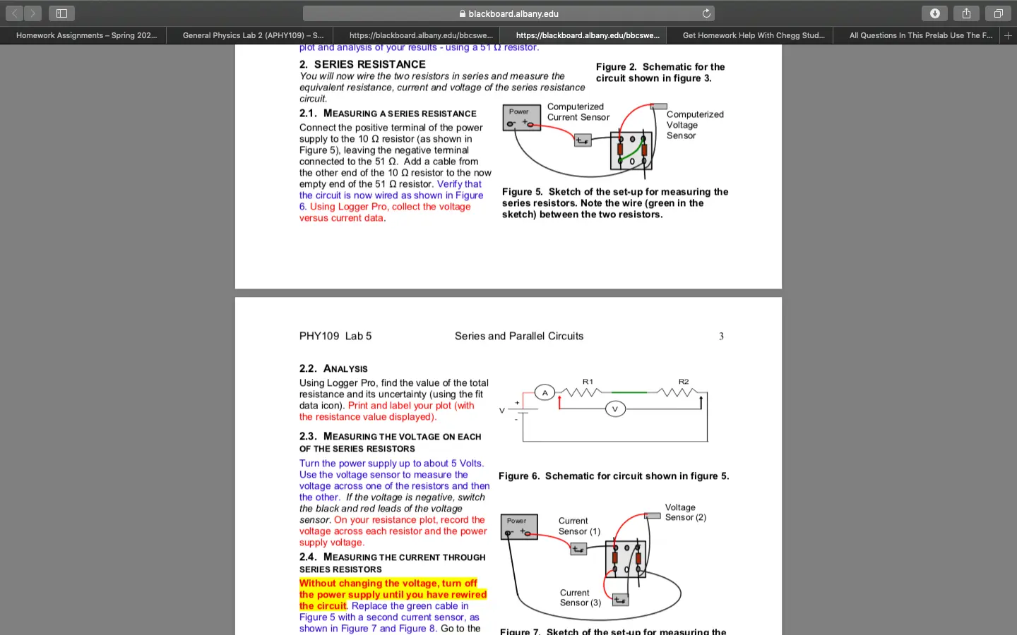
2.1. MEASURING A SERIES RESISTANCE
Connect the positive terminal of the power
supply to the 10 Q resistor (as shown in
Figure 5), leaving the negative terminal
connected to the 51 Q. Add a cable from
the other end of the 10 Q resistor to the now
empty end of the 51 Q resistor. Verify that
the circuit is now wired as shown in Figure
6. Using Logger Pro, collect the voltage
versus current data.
Power
Get Homework Help With Chegg Stud...
Figure 2. Schematic for the
circuit shown in figure 3.
Computerized
Current Sensor
☑
Computerized
Voltage
Sensor
Figure 5. Sketch of the set-up for measuring the
series resistors. Note the wire (green in the
sketch) between the two resistors.
PHY109 Lab 5
Series and Parallel Circuits
3
2.2. ANALYSIS
Using Logger Pro, find the value of the total
resistance and its uncertainty (using the fit
data icon). Print and label your plot (with
the resistance value displayed).
2.3. MEASURING THE VOLTAGE ON EACH
OF THE SERIES RESISTORS
Turn the power supply up to about 5 Volts.
Use the voltage sensor to measure the
voltage across one of the resistors and then
the other. If the voltage is negative, switch
the black and red leads of the voltage
sensor. On your resistance plot, record the
voltage across each resistor and the power
supply voltage.
2.4. MEASURING THE CURRENT THROUGH
SERIES RESISTORS
Without changing the voltage, turn off
the power supply until you have rewired
the circuit. Replace the green cable in
Figure 5 with a second current sensor, as
shown in Figure 7 and Figure 8. Go to the
R1
V
R2
Figure 6. Schematic for circuit shown in figure 5.
Voltage
Sensor (2)
Power
Current
Sensor (1)
Current
Sensor (3)
Figure 7. Sketch of the set-up for measuring the
All Questions In This Prelab Use The F...
+
Homework Assignments - Sprin... General Physics Lab 2 (APHY10...
https://blackboard.albany.edu/b...
blackboard.albany.edu
https://blackboard.albany.edu/b...
Turn the power supply up to about 5 Volts.
Use the voltage sensor to measure the
voltage across one of the resistors and then
the other. If the voltage is negative, switch
the black and red leads of the voltage
sensor. On your resistance plot, record the
voltage across each resistor and the power
supply voltage.
2.4. MEASURING THE CURRENT THROUGH
SERIES RESISTORS
https://blackboard.albany.edu/b...
Figure 6. Schematic for circuit shown in figure 5.
Voltage
Sensor (2)
Power
Current
Sensor (1)
Current
Sensor (3)
Figure 7. Sketch of the set-up for measuring the
currents through both series resistors. The
second current sensor should be connected to
channel 3.
Without changing the voltage, turn off
the power supply until you have rewired
the circuit. Replace the green cable in
Figure 5 with a second current sensor, as
shown in Figure 7 and Figure 8. Go to the
second page of the Logger Pro software to
see the graph of I₁ (the current through the
first sensor) and 12 (the current through the
second sensor) versus time. Turn the power
on and click on "Collect" in Logger Pro. You should
see plots of the current measured by the two
different sensors, plotted versus time. Print and label
your plot.
3. PARALLEL RESISTANCE
You will now wire the two resistors in parallel and
measure the equivalent resistance, current and
voltage of the parallel resistance circuit.
3.1. MEASURING A PARALLEL RESISTANCE
Go back to page one of the Logger Pro
software. Connect the two resistors in
parallel as shown in Figure 9 (a photograph
of the circuit wired in parallel is printed on
the last page of this lab). Verify that the
circuit now wired as shown in Figure 10.
Collect the voltage versus current data.
3.2. ANALYSIS
Using Logger Pro, find the value of the total
resistance and its uncertainty (using the fit
data icon). Print and label your plot (with the
resistance value displayed).
A1
A3
Figure 8. Schematic for circuit shown in
figure 7.
Power
Current
Sensor (1)
Voltage
Sensor (2)
Figure 9. Sketch of the set-up for measuring the
parallel resistors. Note the two cables (green in
the sketch) between the two resistors.
Get Homework Help With Cheg...
All Questions In This Prelab Us...
+
Homework Assignments - Sprin... General Physics Lab 2 (APHY10...
https://blackboard.albany.edu/b...
blackboard.albany.edu
https://blackboard.albany.edu/b...
You will now wire the two resistors in parallel and
measure the equivalent resistance, current and
voltage of the parallel resistance circuit.
3.1. MEASURING A PARALLEL RESISTANCE
Go back to page one of the Logger Pro
software. Connect the two resistors in
parallel as shown in Figure 9 (a photograph
of the circuit wired in parallel is printed on
the last page of this lab). Verify that the
circuit now wired as shown in Figure 10.
Collect the voltage versus current data.
3.2. ANALYSIS
Using Logger Pro, find the value of the total
resistance and its uncertainty (using the fit
data icon). Print and label your plot (with the
resistance value displayed).
https://blackboard.albany.edu/b...
Figure 8. Schematic for circuit shown in
figure 7.
Power
Current
Sensor (1)
Voltage
Sensor (2)
Figure 9. Sketch of the set-up for measuring the
parallel resistors. Note the two cables (green in
the sketch) between the two resistors.
PHY109 Lab 5
Series and Parallel Circuits
3.3. MEASURING THE VOLTAGE ON THE PARALLEL RESISTORS
Set the power supply voltage to about 5 V. Using the voltage sensor, measure the voltage across
each resistor. On your resistance plot, record the voltage across each resistor and the power
supply voltage.
3.4. MEASURING THE CURRENT THROUGH EACH
PARALLEL RESISTOR
Without changing the voltage, turn off the power
supply until you have rewired the circuit. Wire
the first resistor directly to the power supply and
replace the green cables in Figure 9 with current
sensors, as shown in Figure 11 and Figure 12. In
the manner of section 2.4 collect current vs time in
Logger Pro. Print and label your plot and record the
power supply voltage on the printout.
4. CLEAN UP
R1
R2
V
Figure 10. Schematic for the circuit shown
in figure 9.
Power
Current
Current
Sensor (3)
Voltage
Sensor (2)
Turn off the power supply. Disconnect all
cables and sensors.
R2
Sensor (1)
Figure 11. Sketch of the set-up for measuring
the parallel resistors.
Figure 12. Schematic for the circuit
shown in figure 11.
LAB REPORT QUESTIONS
Each question needs to be answered in a separate paragraph in the results section of your
Get Homework Help With Cheg...
All Questions In This Prelab Us...
+
check_circle الجواب — حل مفصل خطوة بخطوة
hourglass_top
🔒
الحل الكامل متاح للمشتركين
اشترك في أرشيف الأسئلة لعرض هذا الحل وآلاف الحلول المفصلة خطوة بخطوة من معلمين معتمدين.