تم الحل ✓
categoryهندسة كهربائية
schoolبكالوريوس
event_available2026-07-15
السؤال
Transcribed Image Text:
7
Series-Parallel DC Circuits
Objective
This exercise will involve the analysis of basic series-parallel DC circuits with resistors. The use of
simple series-only and parallel-only sub-circuits is examined as one technique to solve for desired
currents and voltages.
Theory Overview
Simple series-parallel networks may be viewed as interconnected series and parallel sub-networks. Each
of these sub-networks may be analyzed through basic series and parallel techniques such as the
application of voltage divider and current divider rules along with Kirchhoff's Voltage and Current Laws.
It is important to identify the most simple series and parallel connections in order to jump to more
complex interconnections.
Equipment
(1) Adjustable DC Power Supply
(1) Digital Multimeter
model:
model:
(1) 1.0 ΚΩ
(1) 1.5 ΚΩ
(1) 2.2 ΚΩ
(1) 4.7 ΚΩ
Schematics
R1
B
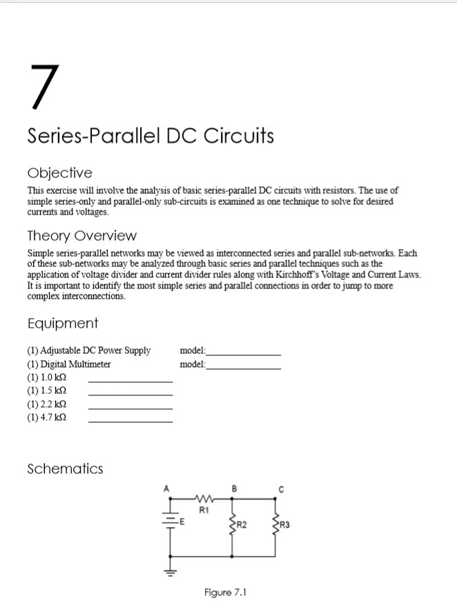
Figure 7.1
R3
A
Figure 7.2
R4
Procedure
1. Consider the circuit of Figure 7.1 with R1-1k, R2 = 1.5k, R3 = 2.2 k and E = 10 volts. R2 is in
parallel with R3. This combination is in series with R1. Therefore, the R2, R3 pair may be treated
as a single resistance to form a series loop with R1. Based on this observation, determine the
theoretical voltages at points A, B, and C with respect to ground. Record these values in Table
7.1. Construct the circuit. Set the DMM to read DC voltage and apply it to the circuit from point
A to ground. Record this voltage in Table 7.1. Repeat the measurements at points B and C,
determine the deviations, and record the values in Table 7.1.
2. Applying KCL to the parallel sub-network, the current entering node B (i.e., the current through
R1) should equal the sum of the currents flowing through R2 and R3. These currents may be
determined through Ohm's Law and/or the Current Divider Rule. Compute these currents and
record them in Table 7.2. Using the DMM as an ammeter, measure these three currents and record
the values along with deviations in Table 7.2.
3. Consider the circuit of Figure 7.2. R2, R3 and R4 create a series sub-network. This sub-network
is in parallel with R1. By observation then, the voltages at nodes A, B and C should be identical
as in any parallel circuit of similar construction. Due to the series connection, the same current
flows through R2, R3 and R4. Further, the voltages across R2, R3 and R4 should sum up to the
voltage at node C, as in any similarly constructed series network. Finally, via KCL, the current
exiting the source must equal the sum of the currents entering R1 and R2.
4. Build the circuit of Figure 7.2 with R1 = 1.0k, R2 = 1.5k, R3 = 2.2k, R4-4.7k and E = 10
volts. Using the series and parallel relations noted in Step 3, calculate the voltages at points B, C,
D and E. Measure these potentials with the DMM, determine the deviations, and record the values
in Table 7.3.
5. Calculate the currents leaving the source and flowing through R1 and R2. Record these values in
Table 7.4. Using the DMM as an ammeter, measure those same currents, compute the deviations,
and record the results in Table 7.4.
Simulation
6. Build the circuit of Figure 7.1 in a simulator. Using the virtual DMM as a voltmeter determine the
voltages at nodes A, B and C, and compare these to the theoretical and measured values recorded
in Table 7.1.
7. Build the circuit of Figure 7.2 in a simulator. Using the DC Operating Point simulation function,
determine the voltages at nodes B, C, D and E, and compare these to the theoretical and measured
values recorded in Table 7.3.
Data Tables
Voltage
Theory
Measured
Deviation
VA
VB
Vo
Current
Theory
R1
R₂
Rs
Table 7.1
Table 7.2
Measured
Deviation
Voltage
Theory
Measured
Deviation
VB
Vo
Vo
VE
Table 7.3
Current
Theory
Source
R1
R2
Table 7.4
Questions
1. Are KVL and KCL satisfied in Tables 7.1 and 7.2?
2. Are KVL and KCL satisfied in Tables 7.3 and 7.4?
Measured
Deviation
3. How would the voltages at A and B in Figure 7.1 change if a fourth resistor equal to 10 k was added
in parallel with R3? What if this resistor was added in series with R3?
4. How would the currents through R1 and R2 in Figure 7.2 change if a fifth resistor equal to 10 k was
added in series with R1? What if this resistor was added in parallel with R1?
check_circle الجواب — حل مفصل خطوة بخطوة
hourglass_top
🔒
الحل الكامل متاح للمشتركين
اشترك في أرشيف الأسئلة لعرض هذا الحل وآلاف الحلول المفصلة خطوة بخطوة من معلمين معتمدين.