تم الحل ✓
categoryالهندسة الميكانيكية
schoolبكالوريوس
event_available2026-07-15
السؤال
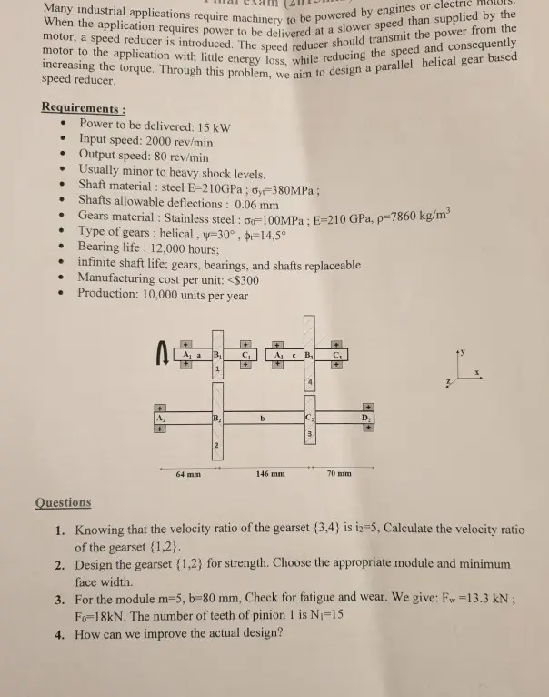
Transcribed Image Text:
Many industrial applications require machinery to be powered by engines or electric
motor, a speed reducer is introduced. The speed reducer should transmit the power from the
motor to the application with little energy loss, while reducing the speed and consequently
When the application requires power to be delivered at a slower speed than supplied by the
increasing the torque. Through this problem, we aim to design a parallel helical gear based
speed reducer.
Requirements:
•
•
•
•
•
•
Power to be delivered: 15 kW
Input speed: 2000 rev/min
Output speed: 80 rev/min
Usually minor to heavy shock levels.
Shaft material: steel E-210GPa; oy-380MPa;
Shafts allowable deflections: 0.06 mm
Gears material: Stainless steel: Go-100MPa; E-210 GPa, p=7860 kg/m³
Type of gears: helical, y-30°, b=14,5°
Bearing life: 12,000 hours;
infinite shaft life; gears, bearings, and shafts replaceable
Manufacturing cost per unit: <$300
•
•
.
Production: 10,000 units per year
A
A₁ a B₁ C₁
Aj c B,
C
+
1
Az
B₂
b
Dy
+
3.
64 mm
2
70 mm
146 mm
7
Questions
1. Knowing that the velocity ratio of the gearset (3,4) is i2-5, Calculate the velocity ratio
of the gearset {1,2}.
2. Design the gearset {1,2} for strength. Choose the appropriate module and minimum
face width.
3. For the module m-5, b=80 mm, Check for fatigue and wear. We give: Fw=13.3 kN ;
Fo 18kN. The number of teeth of pinion 1 is N₁-15
4. How can we improve the actual design?
For manufacturing cost optimization, we adopt a symmetric configuration of the gear train
where the gearset {1,2} has the same properties as the gearset (3,4). We adopt the following
parameters m-5, b=80 mm; N₁-15.
5. Calculate the masses of the gears (2) and (3). (They can be assimilated to disks).
6. Determine the magnitude and the direction of the forces applied on gears {2} and {3}.
7. Draw the free body diagram of shaft b in XY and XZ plans and calculate the reactions.
The weights of the gears (2) and (3) are respectively P2-694 N; P3-27 N
8. Design the shaft "b" based on strength criterion. (Axial forces can be neglected so far)
9. Draw the final design of the shaft. Justify your design.
10. Select the appropriate angular contact ball bearing A2 holding shaft "b". We give the
amplitude of axial forces applied on the bearing A2: Fa(A2) = 1102N. L10-106
revolutions; a=3.
check_circle الجواب — حل مفصل خطوة بخطوة
hourglass_top
🔒
الحل الكامل متاح للمشتركين
اشترك في أرشيف الأسئلة لعرض هذا الحل وآلاف الحلول المفصلة خطوة بخطوة من معلمين معتمدين.