تم الحل ✓
categoryالهندسة الكهربائية
schoolبكالوريوس
event_available2026-07-15
السؤال
Transcribed Image Text:
Tutorial Questions: OTA-C Filters
1. Draw an OTA-C lossy integrator circuit and derive its transfer function.
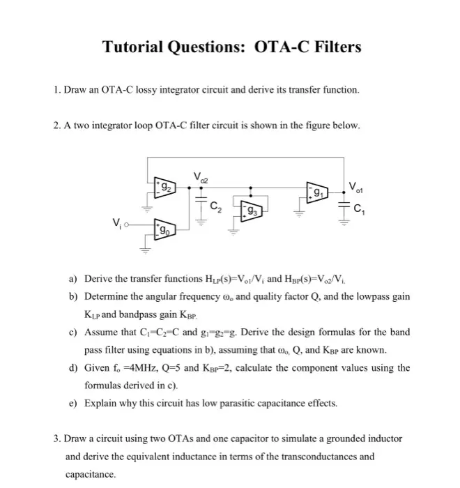
2. A two integrator loop OTA-C filter circuit is shown in the figure below.
92
Vo
9
H
91
93
C₁
555
V01
HH
a) Derive the transfer functions HLP(S)-Vol/V; and HBP(S)-Voz/Vi.
b) Determine the angular frequency and quality factor Q, and the lowpass gain
KLP and bandpass gain KBP.
c) Assume that C₁-C2-C and gi-g-g. Derive the design formulas for the band
pass filter using equations in b), assuming that o, Q, and KBP are known.
d) Given fo =4MHz, Q-5 and KBP-2, calculate the component values using the
formulas derived in c).
e) Explain why this circuit has low parasitic capacitance effects.
3. Draw a circuit using two OTAs and one capacitor to simulate a grounded inductor
and derive the equivalent inductance in terms of the transconductances and
capacitance.
check_circle الجواب — حل مفصل خطوة بخطوة
hourglass_top
🔒
الحل الكامل متاح للمشتركين
اشترك في أرشيف الأسئلة لعرض هذا الحل وآلاف الحلول المفصلة خطوة بخطوة من معلمين معتمدين.