تم الحل ✓
categoryهندسة كيميائية
schoolبكالوريوس
event_available2026-07-15
السؤال
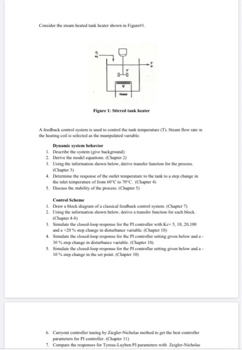
Transcribed Image Text:
Consider the steam heated tank heater shown in Figure 1.
Figure 1: Stirred tank heater
A feedback control system is used to control the tank temperature (T). Steam flow rate in
the heating coil is selected as the manipulated variable.
Dynamic system behavior
1. Describe the system (give background)
2. Derive the model equations. (Chapter 2)
3. Using the information shown below, derive transfer function for the process.
(Chapter 3)
4. Determine the response of the outlet temperature to the tank to a step change in
the inlet temperature of from 60°C to 70°C. (Chapter 4)
5. Discuss the stability of the process. (Chapter 5)
Control Scheme
1. Draw a block diagram of a classical feedback control system. (Chapter 7)
2. Using the information shown below, derive a transfer function for each block.
(Chapter 4-8)
3. Simulate the closed-loop response for the PI controller with Ke-5, 10, 20,100
and a +20% step change in disturbance variable. (Chapter 10)
4. Simulate the closed-loop response for the Pl controller setting given below and a-
30% step change in disturbance variable. (Chapter 10)
5. Simulate the closed-loop response for the Pl controller setting given below and a-
10% step change in the set point. (Chapter 10)
6. Carryout controller tuning by Ziegler-Nicholas method to get the best controller
parameters for Pl controller. (Chapter 11)
7. Compare the responses for Tyreus-Luyben Pl parameters with Zeigler-Nicholas
6. Carryout controller tuning by Ziegler-Nicholas method to get the best controller
parameters for PI controller. (Chapter 11)
7. Compare the responses for Tyreus-Luyben PI parameters with Zeigler-Nicholas
PI. (Chapter 11)
8. Carryout out stability analysis using Bode criterion. (Chapter 13)
9. Use appropriate values of gain margin and phase margin to design the controller.
(Chapter 13)
10. Design a closed loop IMC controller that gives a first order plus time delay
response for a step change. Assuming that the model perfectly captures the
process behavior. (Chapter 11)
11. Simulate the control loop but assume additional time delay of 1 min in the
measuring element for a 10% change in the set point.
Data:
Volume of the tank-1000 L
Volumetric flow rate=200 L/min
T₁ = 60°C, T = 80°C,
Transfer function for the control valve = G, =
0.5+1
Transfer function for the measuring element= Gm =
0.33s+1
Use Matlab-Simulink to complete this project
check_circle الجواب — حل مفصل خطوة بخطوة
hourglass_top
🔒
الحل الكامل متاح للمشتركين
اشترك في أرشيف الأسئلة لعرض هذا الحل وآلاف الحلول المفصلة خطوة بخطوة من معلمين معتمدين.