تم الحل ✓
categoryالفيزياء
schoolبكالوريوس
event_available2026-07-15
السؤال
Transcribed Image Text:
(This problem is from Prof. Aaron Lanterman.) Coil guns use electromagnetism to accelerate
metal bolts to high speeds. The bolt is placed within the coils of an inductor, near one end. When
a current is run through the coils, the bolt is pulled towards the center of the inductor. Precise
timing is needed, since the current must be shut off just before the bolt passes through the center
of the coil so that it is allowed to leave the coil instead of being pulled back in.
Effective coil guns require large inductor currents. Batteries can store tremendous amounts
of electric charge, but they usually cannot provide those charges very quickly; there are practical
limits to the amount of current that a battery may provide. A common way to get around this
limitation of batteries is to charge a capacitor and use charge from the capacitor to power the coil.
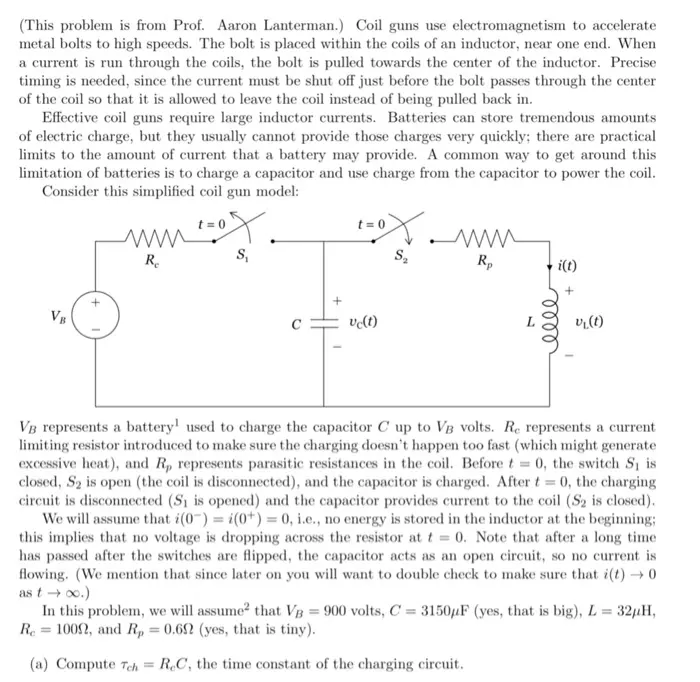
Consider this simplified coil gun model:
+
t=0
ww
Re
S₁
t=0
www
Rp
i(t)
ve(t)
eeee
+
V₁(t)
VB represents a battery used to charge the capacitor C up to VB volts. Re represents a current
limiting resistor introduced to make sure the charging doesn't happen too fast (which might generate
excessive heat), and R, represents parasitic resistances in the coil. Before t = 0, the switch S₁ is
closed, S2 is open (the coil is disconnected), and the capacitor is charged. After t = 0, the charging
circuit is disconnected (S₁ is opened) and the capacitor provides current to the coil (S2 is closed).
We will assume that i(0) = i(0+) = 0, i.e., no energy is stored in the inductor at the beginning;
this implies that no voltage is dropping across the resistor at t=0. Note that after a long time
has passed after the switches are flipped, the capacitor acts as an open circuit, so no current is
flowing. (We mention that since later on you will want to double check to make sure that i(t) → 0
as t→ ∞o.)
In this problem, we will assume that VB = 900 volts, C = 3150µF (yes, that is big), L = 32μH,
Re =1000, and Rp = 0.69 (yes, that is tiny).
(a) Compute Tch RC, the time constant of the charging circuit.
=
(b) A common rule of thumb is to assume that an RC circuit has effectively reached its "final
value" within 5 time constants. Compute 57ch. We will consider this the amount of time
it takes to be ready to fire (assuming we start the charging process with a fully discharged
capacitor). Justify our rule of thumb by computing VB[1-exp(-5)] and saying "ooooh" and
"aaaaah" at how close that is to VB.
(c) For this part and all the remaining parts, we can ignore the actual battery VB and Re; they
were just there to charge up the capacitor. Redraw the rest of the circuit in the Laplace do-
main, i.e., denote the resistor with an impedance R, the capacitance with impedance 1/(SC),
and the inductor with an impedance sL. The inductor is assumed to have no stored en-
ergy at the start of the problem, but the capacitor has an initial condition of v(0) = VB.
You can accommodate this initial condition by placing a voltage source with voltage v(0)/s
in series with the impedance of 1/(SC), or by placing a current source of Cu(0) in par-
allel with an impedance of 1/(sC). Both these configurations are shown, for instance, on
slide 8 of http://web.cecs.pdx.edu/"ece2xx/ECE222/Slides/LaplaceCircuits.pdf or
slide 9 of http://www.ee.nthu.edu.tw/"sdyang/Courses/Circuits/Ch13 Std.pdf or the
"s-Domain equivalent circuits and impedances" section of the wikipedia page on the Laplace
transform: http://en.wikipedia.org/wiki/Laplace transform. You should use the ver-
sion that models the capacitance with an initial condition as an impedance in series with a
voltage source. (Be extra careful with the direction of current arrows and the labeling of
voltage differences.)
(d) Write the KVL equation for this loop in terms of I(s), the Laplace transform of the current
i(t) flowing through the inductor for t≥ 0. Rearrange your equation so that it has I(s) on
the left and everything else on the right.
(e) Take the inverse Laplace transform of your expression from part (d) to find i(t) for t > 0.
Note that the circuit is over damped, so i(t) is a sum of decaying sinusoids. Express your
answer in the form i(t) = A exp(-at)u(t) + B exp(-ẞt)u(t), giving specific values for A, B,
a, and B.
(f) By taking the derivative of the expression for i(t) you found in part (e) and setting it equal
to zero, find the time tmax at which i(t) achieves its maximum. Then find i(tmax), the actual
maximum current.
(g) Find an expression for the damping factor for this circuit as a function of component values.
Given the values of C and L used above, what value of R, would result in a critically
damped system, i.e., a damping factor of <= 1?
(h) Using Laplace transforms, find i(t) using the value of Rp you found in part (g); let's add the
subscript "e" for "critical." The solution now has the form i(t) = Feu(t) + Gteu(t).
Be sure to specify values for F, G, and 7.
(i) By taking the derivative of the expression for i,(t) you found in part (h) and setting it equal to
zero, find the time tmax at which i(t) achieves its maximum. Then find ic(tmax) and compare
it with the peak magnitude of the overdamped system you found in part (h). Considering
that we want to quickly send really high currents into the coil, which would be preferable:
overdamped or critically damped?3
check_circle الجواب — حل مفصل خطوة بخطوة
hourglass_top
🔒
الحل الكامل متاح للمشتركين
اشترك في أرشيف الأسئلة لعرض هذا الحل وآلاف الحلول المفصلة خطوة بخطوة من معلمين معتمدين.