تم الحل ✓
categoryالهندسة الكهربائية
schoolبكالوريوس
event_available2026-07-15
السؤال
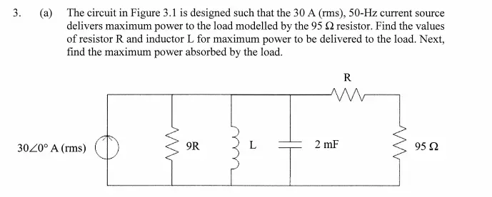
Transcribed Image Text:
3.
(a) The circuit in Figure 3.1 is designed such that the 30 A (rms), 50-Hz current source
delivers maximum power to the load modelled by the 95 2 resistor. Find the values
of resistor R and inductor L for maximum power to be delivered to the load. Next,
find the maximum power absorbed by the load.
R
ww
30/0° A (rms)
9R
L
2 mF
95 Ω
check_circle الجواب — حل مفصل خطوة بخطوة
hourglass_top
🔒
الحل الكامل متاح للمشتركين
اشترك في أرشيف الأسئلة لعرض هذا الحل وآلاف الحلول المفصلة خطوة بخطوة من معلمين معتمدين.