تم الحل ✓
categoryالهندسة الميكانيكية
schoolبكالوريوس
event_available2026-07-15
السؤال
Transcribed Image Text:
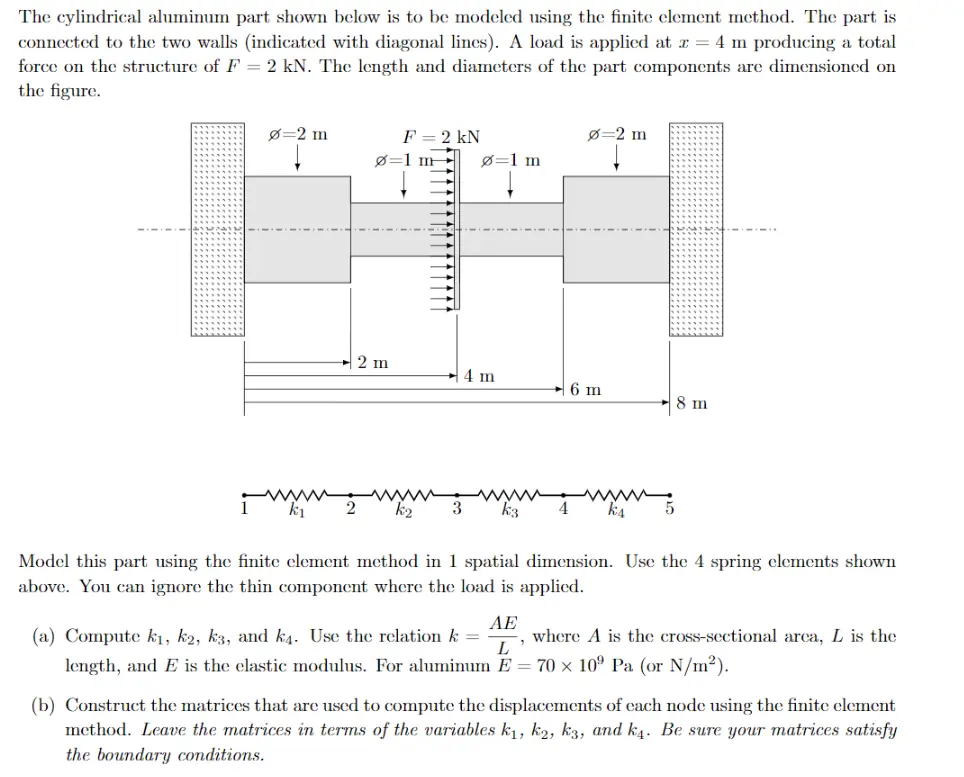
The cylindrical aluminum part shown below is to be modeled using the finite element method. The part is
connected to the two walls (indicated with diagonal lines). A load is applied at x = 4 m producing a total
force on the structure of F = 2 kN. The length and diameters of the part components are dimensioned on
the figure.
=2 m
↓
F = 2 kN
Ø=1 m
0=2 m
Ø=1 m
2 m
4 m
6 m
8 m
k1
2
k2
3
k3
k4
5
Model this part using the finite element method in 1 spatial dimension. Use the 4 spring elements shown
above. You can ignore the thin component where the load is applied.
(a) Compute k₁, k2, k3, and k4. Use the relation k =
AE
L
where A is the cross-sectional area, L is the
length, and E is the elastic modulus. For aluminum E = 70 x 109 Pa (or N/m²).
(b) Construct the matrices that are used to compute the displacements of each node using the finite element
method. Leave the matrices in terms of the variables k₁, k2, k3, and k4. Be sure your matrices satisfy
the boundary conditions.
check_circle الجواب — حل مفصل خطوة بخطوة
hourglass_top
🔒
الحل الكامل متاح للمشتركين
اشترك في أرشيف الأسئلة لعرض هذا الحل وآلاف الحلول المفصلة خطوة بخطوة من معلمين معتمدين.