تم الحل ✓
categoryالهندسة الكهربائية
schoolبكالوريوس
event_available2026-07-15
السؤال
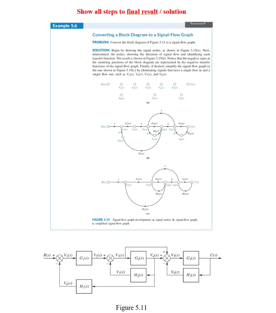
Transcribed Image Text:
Example 5.6
Show all steps to final result / solution
Converting a Block Diagram to a Signal-Flow Graph
PROBLEM: Convert the block diagram of Figure 5.11 to a signal-flow graph.
SOLUTION: Begin by drawing the signal nodes, as shown in Figure 5.19(a). Next,
interconnect the nodes, showing the direction of signal flow and identifying each
transfer function. The result is shown in Figure 5.19(b). Notice that the negative signs at
the summing junctions of the block diagram are represented by the negative transfer
functions of the signal-flow graph. Finally, if desired, simplify the signal-flow graph to
the one shown in Figure 5.19(c) by eliminating signals that have a single flow in and a
single flow out, such as V₂(s), V6(s), V(s), and Vs(s).
0%
R(s) O
о
V₁(0)
о
V₂la)
о
V(3)
о
03
Vy(s)
V(3)
o
O CIs)
Vals)
V(3)
о
V8(3)
(a)
G₁(8)
1
G₂(3)
1
G₁(3)
Rs) O
Cis)
V₁(3) V₁(3)
Vy(s)
Vals) Ve(s)
Hs)
-14
Hyls)
V-0)
V8(3)
Vis)
H₁(3)
(b)
G₁(s)
Gy(1)
Gy(5)
CU)
R(3)
V₁(s)
Vs)
Va(s) Vg(s)
-H₂(s)
-H3(3)
-H(s)
(c)
FIGURE 5.19 Signal-flow graph development: a. signal nodes; b. signal-flow graph:
c. simplified signal-flow graph
R(s) +
V₁(s)
V₂(s)+
V3(s)
V4(s) + V5(s)
C(s)
G₁(s)
G₂(s)
G3($)
V₁(s)
V8($)
H2(8)
H3(5)
V6(s)
H₁(s)
Figure 5.11
check_circle الجواب — حل مفصل خطوة بخطوة
hourglass_top
🔒
الحل الكامل متاح للمشتركين
اشترك في أرشيف الأسئلة لعرض هذا الحل وآلاف الحلول المفصلة خطوة بخطوة من معلمين معتمدين.