تم الحل ✓
categoryالهندسة الكهربائية
schoolبكالوريوس
event_available2026-07-15
السؤال
Transcribed Image Text:
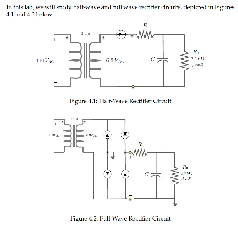
In this lab, we will study half-wave and full wave rectifier circuits, depicted in Figures
4.1 and 4.2 below.
110 VAC
+
110VAC
1: a
R
Ro
C
2.2ΚΩ
6.3 VAC
(load)
Figure 4.1: Half-Wave Rectifier Circuit
1: a
6.3VAC
R
Ro
C
2.2ΚΩ
(load)
Figure 4.2: Full-Wave Rectifier Circuit
These rectifier circuits are shown configured with low-pass RC filters prior to the load.
The unfiltered rectified sine wave signals appear at the yellow terminals as function
x(t).
Both rectifier circuits can be idealized as shown in Figure 4.3, where here x(t) repre-
sents either the half-wave or the full-wave rectified signal.
+
R
Ro
v(t)
Diode Rectifier
(Half-Wave / Full-Wave)
x(t)
C
y(t)
2.2k
(load)
Figure 4.3: Model for Analyzing Rectified Power Supplies
Recall the half-wave rectified sine wave is given over one period by:
A sin () 0≤t≤
Xhw(t)
0
T≤t≤ To
and the full-wave rectified sine wave is given over one period by:
Xfw(t) = A sin
Finally, recall that in class we have shown that the Fourier coefficients for a half-wave
rectified sine wave are:
*(1-k²)
fork =0, ±2, 14, ...
Хали
0
for k odd and k + ±1
kA
for k = ±1
5. For a 6.3 VRMS 60 Hz input, determine the value of the DC component of x(t) for
a
a) half-wave rectifier
b) full-wave rectifier
check_circle الجواب — حل مفصل خطوة بخطوة
hourglass_top
🔒
الحل الكامل متاح للمشتركين
اشترك في أرشيف الأسئلة لعرض هذا الحل وآلاف الحلول المفصلة خطوة بخطوة من معلمين معتمدين.