تم الحل ✓
categoryفيزياء
schoolبكالوريوس
event_available2026-07-15
السؤال
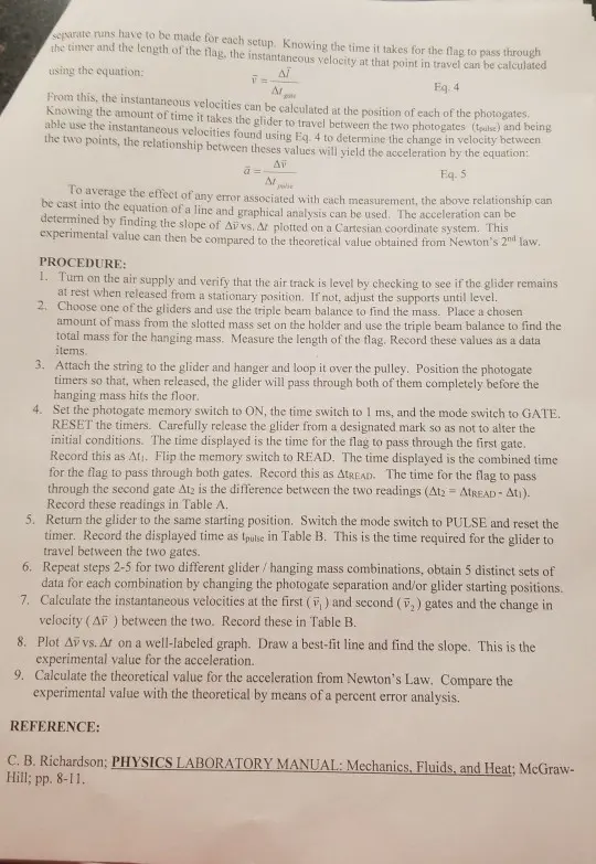
Transcribed Image Text:
separate runs have to be made for each setup. Knowing the time it takes for the flag to pass through
the timer and the length of the flag, the instantaneous velocity at that point in travel can be calculated
using the equation:
Al
F =
M
Eq. 4
From this, the instantaneous velocities can be calculated at the position of each of the photogates.
Knowing the amount of time it takes the glider to travel between the two photogates (pulse) and being
able use the instantaneous velocities found using Eq. 4 to determine the change in velocity between
the two points, the relationship between theses values will yield the acceleration by the equation:
Δε
ΔΕ
polie
Eq. 5
To average the effect of any error associated with each measurement, the above relationship can
be cast into the equation of a line and graphical analysis can be used. The acceleration can be
determined by finding the slope of Av vs. Ar plotted on a Cartesian coordinate system. This
experimental value can then be compared to the theoretical value obtained from Newton's 2nd law.
PROCEDURE:
1. Turn on the air supply and verify that the air track is level by checking to see if the glider remains
at rest when released from a stationary position. If not, adjust the supports until level.
2. Choose one of the gliders and use the triple beam balance to find the mass. Place a chosen
amount of mass from the slotted mass set on the holder and use the triple beam balance to find the
total mass for the hanging mass. Measure the length of the flag. Record these values as a data
items.
3. Attach the string to the glider and hanger and loop it over the pulley. Position the photogate
timers so that, when released, the glider will pass through both of them completely before the
hanging mass hits the floor.
4. Set the photogate memory switch to ON, the time switch to 1 ms, and the mode switch to GATE.
RESET the timers. Carefully release the glider from a designated mark so as not to alter the
initial conditions. The time displayed is the time for the flag to pass through the first gate.
Record this as Ati. Flip the memory switch to READ. The time displayed is the combined time
for the flag to pass through both gates. Record this as AtREAD. The time for the flag to pass
through the second gate At2 is the difference between the two readings (At2 - AtREAD - Ati).
Record these readings in Table A.
5. Return the glider to the same starting position. Switch the mode switch to PULSE and reset the
timer. Record the displayed time as tpulse in Table B. This is the time required for the glider to
travel between the two gates.
6. Repeat steps 2-5 for two different glider/hanging mass combinations, obtain 5 distinct sets of
data for each combination by changing the photogate separation and/or glider starting positions.
7. Calculate the instantaneous velocities at the first (,) and second (2) gates and the change in
velocity (A) between the two. Record these in Table B.
8. Plot Av vs. Af on a well-labeled graph. Draw a best-fit line and find the slope. This is the
experimental value for the acceleration.
9. Calculate the theoretical value for the acceleration from Newton's Law. Compare the
experimental value with the theoretical by means of a percent error analysis.
REFERENCE:
C. B. Richardson; PHYSICS LABORATORY MANUAL: Mechanics, Fluids, and Heat; McGraw-
Hill; pp. 8-11.
PURPOSE: To apply Newton's 2nd law of motion to a system of particles using an air track to
simulate a friction free environment. The calculated experimental results for the acceleration of the
system will then be compared to the acceleration of the system as predicted by Newton's laws.
EQUIPMENT: Air-track and supply, triple beam balance, various size gliders w/ flag, master and
slave photogate timers, pulley and string, mass-holders and set of slotted masses, meter stick.
INTRODUCTION: Newton's Second Law of Motion states that if a net force is acting on a body, it
will produce acceleration in the direction of the force. The acceleration is directly proportional to the
force, and inversely proportional to the mass of the body. The application of this law can be extended
to a system of particles as shown in the setup below. A hanging mass is attached to the glider by a
light, flexible string suspended from a "frictionless" pulley.
Glider
Photogate
Timers
Mass
The weight of the hanging mass provides the driving force of the system. Since tension in the
string is uniform, which means that the tensional force pulling up on the hanging mass is equal and
opposite to the tensional force pulling on the glider, it contributes no net force. The air track
eliminates any frictional forces on the glider, so the only force acting on the system is the weight of
the hanging mass W2. By Newton's 2nd law, F = Ma, the net force applied by the hanging mass
accelerates the system of particles, m,+m,. The mass of the system, M, is the sum of the glider
mass and the hanging mass. These relationships can be represented with the following equations:
Mass of the System: M=m, +m
Newton's 2nd Law: F = Ma
Driving Force: W₁ = m₁g,
Eq. 1
Eq. 2
Equating Eq. 1 and Eq. 2:
F = W₁₂
(m,+m, Ja=m₁g
a =
m₂
(m, +m₂
g
Eq. 3
Solve for the acceleration, a:
An experimental value for the acceleration of the system cannot be measured directly but can be
derived through calculation and graphical methods. The master and slave photogate timers are used to
measure both the time it takes the glider to travel between the two photogates (tpulse) as well as the
me it takes for the flag on top of the glider to pass through each gate (tgate). For this reason, two
DATA & CALCULATIONS-1" Combination
Flag Length:
Glider Mass:
Table A.1.
9.9 cm=0.099m
191.0 Hanging Mass: 25.3g
Run #
1
2
At (sec.)
2465
•2453
ATREAD (sec.)
3312
•$329 Accent
Atz AlREAD Ati (sec.)
0847
040876
3
4
•2419 Acconds
2428 D
0.3338
0.0919
5
•2417 Seconds
0.3392 Accord 0.0964
0.3443 mult
0.1026
√ √ AV
Table B.1
Run #
v, (m/s)
V₁(m/s)
Av (m/s)
Spulse (sec.)
1
1.1688 MA
0.7672
0.7145
2
0.4036m 1.130/m/d
0.7269 0.75774
3
0.4093
•0773 m/s
0.668
0.70004
4
0.4077m
1.0270mA
06193 065324
5
0.4096m
019649 m 0.5553mN 0.59054
Δυ
Acceleration Experimental (Determined from the slope of your graph.)
At
check_circle الجواب — حل مفصل خطوة بخطوة
hourglass_top
🔒
الحل الكامل متاح للمشتركين
اشترك في أرشيف الأسئلة لعرض هذا الحل وآلاف الحلول المفصلة خطوة بخطوة من معلمين معتمدين.